
|
|
Forum Index : Microcontroller and PC projects : PicoMite Alpha Firmware - a27 onwards - starting on displays
| Author | Message | ||||
| panky Guru Joined: 02/10/2012 Location: AustraliaPosts: 1114 |
@palcal, Thanks, I noted Geoff's helpful response. I can get the calibrate to complete as per my detailed description above (with a good deal of trial and error[s]) and once it is calibrated successfully, I can re-calibrate as often as I like with any length of touch duration on the targets - the problem is the issue of touch duration immediately after a firmware update. Doug. ... almost all of the Maximites, the MicromMites, the MM Extremes, the ArmMites, the PicoMite and loving it! |
||||
palcal Guru Joined: 12/10/2011 Location: AustraliaPosts: 1989 |
A weird one ? "It is better to be ignorant and ask a stupid question than to be plain Stupid and not ask at all" |
||||
TassyJim Guru Joined: 07/08/2011 Location: AustraliaPosts: 6269 |
I have finally got around to connecting a ILI9341 display. I agree that the initial calibrate is touchy to say the least. I also started with RL orientation and got a silly calibrate. GUI CALIBRATE 0, 4385, 0, -1033, 9223372036854775807 That last number in HEX is: 7FFF FFFF FFFF FFFF Using normal Landscape (not reversed) give a more realistic set of values: GUI CALIBRATE 0, 4173, -531, -3817, 564 for the first attempt and GUI CALIBRATE 0, 308, 297, 964, 700 for the second with longer presses. Jim VK7JH MMedit |
||||
| Mixtel90 Guru Joined: 05/10/2019 Location: United KingdomPosts: 7871 |
I use my display in RL too. Managed to get it to calibrate but test didn't appear to work - just a blank screen. I eventually tried to draw a line in from one edge and the line appeared from the opposite edge! Response to touch was fully reversed and inverted! Re-configured the display for L and the text was upside down but touch was correct. Re-configured again as RL and everything is working correctly now. <Phew!> GUI CALIBRATE 0, 369, 308, 898, 686 I'd previously had all sorts of junk in here including negative values and insanely high ones. I think the hysteresis might have helped in the initial calibration, Peter. Doc update: PicoMite docs a41.zip I've also added some info to OPTION MEMORY in a36 to make it a bit easier to follow (I think!). . Edited 2021-06-29 16:57 by Mixtel90 Mick Zilog Inside! nascom.info for Nascom & Gemini Preliminary MMBasic docs & my PCB designs |
||||
| TrevorC Newbie Joined: 15/07/2020 Location: United KingdomPosts: 15 |
I can confirm the above comments about GUI CALIBRATE and it now works as expected. Still a bit strange. Settings below: OPTION AUTORUN 1 OPTION SDCARD GP17, 10 OPTION SYSTEM SPI GP18,GP19,GP16 OPTION SYSTEM I2C GP0,GP1 OPTION LCDPANEL ILI9341, RLANDSCAPE,GP22,GP26,GP27 OPTION TOUCH GP21,GP20 GUI CALIBRATE 0, 3775, 3834, -881, -659 Thanks. |
||||
| matherp Guru Joined: 11/12/2012 Location: United KingdomPosts: 10246 |
a42 PicomiteV5.07.00a42.zip Fixes pause bug Lots of new PIO stuff - limited testing PIO() function PIO(PINCTRL no_side_set_pins [,no_set_pins] [,no_out_pins] [,IN base] [,side_set_base] [,set_base]) helper function to calculate the value of pinctrl for the INIT MACHINE command PIO(EXECCTRL jmp_pin ,wrap_target, wrap helper function to calculate the value of execctrl for the INIT MACHINE command PIO(SHIFTCTRL push_threshold [,pull_threshold] [,autopush] [,autopull]) helper function to calculate the value of shiftctrl for the INIT MACHINE command PIO(FSTAT pio) returns the value of the FSTAT register for the pio specified PIO(FDEBUG pio) returns the value of the FSDEBUG register for the pio specified PIO(FLEVEL pio) returns the value of the FLEVEL register for the pio specified PIO command PIO EXECUTE pio, state_machine, instruction% Immediately executes the instruction on the pio and state machine specified. PIO WRITE pio, state_machine, count, data0 [,data1....] writes the data elements to the pio and state machine specified. The write is blocking so the state machine needs to be able to take the data supplied. NB: this command will probably need additional capability in future releases PIO READ pio, state_machine, count, data%() reads the data elements from the pio and state machine specified. The read is non-blocking so the stat machine needs to be able to supply the data requested. NB: this command will probably need additional capability in future releases PIO PROGRAM pio, program_array%() Programs one of the two PIO with a specific program. The program_array%() will always be 8 elements long (32x16bit instructions) and unneeded instructions should be filled with MOV y,y (NOP) PIO INIT MACHINE pio, statemachine, clockspeed, PINCTRL register EXECCTRL register, SHIFTCTRL register This says to set up a statemachine for the specified PIO with a given clock speed. The user is then required to specify the three registers which control how the PIO will operate. See the manual for details. It is anticipated that eventually the assembler will be able to generate the register values for the user along with the program array based on the defined assembler directives. something in Basic PIO START pio, statemachine Starts or restarts a specific state machine PIO STOP pio, statemachine Stops a specific state machine |
||||
| lizby Guru Joined: 17/05/2016 Location: United StatesPosts: 3362 |
All very well with the PIC32MZ, but where is the MMX available? I couldn't find one at micromite.org, circuitgizmos.com, rictech.nz--and at what cost for a populated board? And what chance for building for someone not comfortable with soldering large surface-mount components? I've provided easily soldered PCB designs for the Pico, and the components (in module form with .1" pin spacing) are readily and cheaply available: RTC module, SD card module, ESP-01 module, SPI ILI9341 or ILI9488. SSD1963 is great for speed, but not for cost. And while noting the considerable value of your time in implementing, if the firmware space is available, what does the PicoMite lose by having this capability? PicoMite, Armmite F4, SensorKits, MMBasic Hardware, Games, etc. on fruitoftheshed |
||||
| matherp Guru Joined: 11/12/2012 Location: United KingdomPosts: 10246 |
The console couldn't work on the ili9488 as it doesn't support reading the video memory because of the MISO problem. Both the ILI9488 and ILI9341 are orientated portrait so there is no support for H/W scrolling in landscape. This means that on the ILI9341 you would need to read each pixel and then re-write to action a line scroll meaning even at 250MHz overclock a scroll take 200mSec. This is simply too slow to be sensibly usable. In addition you would presumably want PS2 keyboard support. So I would need to do a weeks work to get a crap result - sorry but NO Edited 2021-06-30 01:32 by matherp |
||||
| phil99 Guru Joined: 11/02/2018 Location: AustraliaPosts: 2611 |
Re scrolling on ILI9341 This might not work for the editor but for display on a data logger I used over write instead, when the screen is full it goes back to the top. A coloured line is used to divide the old and new text. You can't scroll but can page up or down by rewriting the whole screen, allowing a few lines of overlap with the previous page so you don't get lost. I kept all the text in memory as a string array, which could used up a lot of space. It might be possible to use the SD card instead. |
||||
| matherp Guru Joined: 11/12/2012 Location: United KingdomPosts: 10246 |
a43 PicomiteV5.07.00a43.zip DEFINEFONT now working OPTION PIN now working |
||||
| matherp Guru Joined: 11/12/2012 Location: United KingdomPosts: 10246 |
a44 PicomiteV5.07.00a44.zip New PIO commands PIO CLEAR pio This stops the pio specified on all statemachines and clears the control registers for the statemachines PINCTRL, EXECTRL, and SHIFTCTRL to defaults PIO PROGRAM LINE pio, line, instruction Programs just the specified line in a PIO program e.g. run the program Dim a%(7)=(&H0001E000E101E081,0,0,0,0,0,0,0) SetPin 1,pio0 PIO program 0,a%() PIO init machine 0,0,100000 PIO start 0,0 The at the command prompt type PIO PROGRAM LINE 0,1, &Hef01 and see the waveform change A complete program can also be done like this, even at the command line setpin 1,pio0 pio clear 0 pio program line 0,0,&He081 pio program line 0,1,&He101 pio program line 0,2,&He000 pio program line 0,3,1 pio init machine 0,0,1000000 pio start 0,0 |
||||
| Volhout Guru Joined: 05/03/2018 Location: NetherlandsPosts: 5059 |
Hi Peter/Mixtel90, I am trying to learn how the sequencer would work, and should be programmed. When I understand this correctly, the "setpin 1,pio0" assigns picomite pin 1 as the base GPIO pin for PIO sequencer 0. Picomite pin 1 is connected to GP0. Meaning GP0 is the base pin for PIO sequencer 0. Correct ? If you execute the following command in the sequencer "out 1,3" the 3 least significant bits of the OSR are send to GP2, GP1, GP0. (pins 4,2,1 of the picomite). Correct ? If I would like to send 3 bits to GP5,4,3 then the instruction would be "out 5,3" (as pin 5 maps to GP3. Or would it be "out 3,3" at the base is GP0, GP3 is at bit 3. Correct ? Thanks in advance for your help... Volhout Edited 2021-06-30 22:32 by Volhout PicomiteVGA PETSCII ROBOTS |
||||
| matherp Guru Joined: 11/12/2012 Location: United KingdomPosts: 10246 |
No: it just says pin one is available to PIO0 for output. The out base pin is set by the pinctrl register - see the ? pin(pinctrl pin,sm) function. As it happens this defaults to a base of zero but if you set the base to something else then the pins effectively number sequentially from the new base. To use GPIO5 with out you would need to set the OUT BASE to at least 1 as out can only address 5 pins (by default 0-4) WARNING: The above is correct AFAIK but I'm learning with the rest of you |
||||
| matherp Guru Joined: 11/12/2012 Location: United KingdomPosts: 10246 |
a45 PicomiteV5.07.00a45.zip KEYPAD and LCD commands now working - see MM2 manual. Note you should use a 3.3V LCD as in the picture - they are available 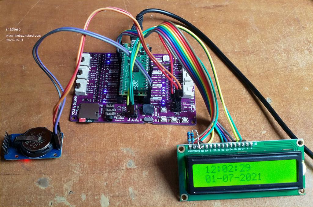 Things to do: Implement the GPS functionality from the Armmites Implement background ADC functionality Implement SOUND That should then be pretty much it for a good usable port with the bonus of the high speed, DIL form factor, and chip specific functionality like PIO in a very cheap package Edited 2021-07-01 21:58 by matherp |
||||
| thwill Guru Joined: 16/09/2019 Location: United KingdomPosts: 4302 |
 I hate to be the one to ask, but are we going to get CSUBs ? My only specific interest at the moment is for porting CMM2 code that makes use of CSUB's auxiliary function as stores of arbitrary binary data for retrieval via PEEK(CFUNADDR, x) and MEMORY COPY. Best wishes, Tom Edited 2021-07-01 22:04 by thwill MMBasic for Linux, Game*Mite, CMM2 Welcome Tape, Creaky old text adventures |
||||
| Mixtel90 Guru Joined: 05/10/2019 Location: United KingdomPosts: 7871 |
You've done a great job, Peter. :) Bits wot I would still love to see... Alternative LCD INIT for i2c LCD displays? They work very nicely with 5v displays and less pins used. Reading pin(24) - high if VBUS is present on otherwise battery operated systems Reading adc3 - VSYS voltage (used as a supply battery monitor) There's no additional hardware needed for these, it's already there and is supported in micropython. Ideally I'd like to see RS485 implemented as this is primarily a controller. I know it's easy enough to use a uart & direction pin for the driver, but some way of handling transmit and receive with CRC and/or checksum generation and checking would be rather cool. I suppose this could be done with a csub though. Mick Zilog Inside! nascom.info for Nascom & Gemini Preliminary MMBasic docs & my PCB designs |
||||
| JohnS Guru Joined: 18/11/2011 Location: United KingdomPosts: 4038 |
If/when there are CSUBs... John |
||||
| Mixtel90 Guru Joined: 05/10/2019 Location: United KingdomPosts: 7871 |
Just wishful thinking on my part. :) Mick Zilog Inside! nascom.info for Nascom & Gemini Preliminary MMBasic docs & my PCB designs |
||||
| matherp Guru Joined: 11/12/2012 Location: United KingdomPosts: 10246 |
This is exactly what PIO is for. The RP2040 doesn't have H/W RS485 support but you can implement it with a PIO program. No need for CSUBs for this. Edited 2021-07-01 23:55 by matherp |
||||
| Mixtel90 Guru Joined: 05/10/2019 Location: United KingdomPosts: 7871 |
While I'm developing... RESTORE <variable$> would be *really* handy! lol e.g. a$="Sample1" RESTORE a$ Sample1: DATA DATA etc... Sample2: DATA DATA etc... Maybe a bit non-standard... :) Mick Zilog Inside! nascom.info for Nascom & Gemini Preliminary MMBasic docs & my PCB designs |
||||
| The Back Shed's forum code is written, and hosted, in Australia. | © JAQ Software 2025 |
