
|
|
Forum Index : Microcontroller and PC projects : Design #3 - PicoMite VGA mini
| Author | Message | ||||
| Mixtel90 Guru Joined: 05/10/2019 Location: United KingdomPosts: 7832 |
I think I've managed it... :) Did away with the analogue inputs. I think they'd be of very limited interest and there's always PicoGAME if someone wants them. Mick Zilog Inside! nascom.info for Nascom & Gemini Preliminary MMBasic docs & my PCB designs |
||||
| Mixtel90 Guru Joined: 05/10/2019 Location: United KingdomPosts: 7832 |
I've updated the PicoMite VGA mini 60 construction pack now. PCB version 1.1 The little pad and hole problem that JLCPCB queried has been sorted out by deleting the little pad and turning the hole into a bigger pad. It should still be usable for a locator pin and do dual purpose as a support pin for a HC-12. If you have ordered boards using the original Gerbers and have told them to delete the hole then, if you wish to fit the standard SD card you will need to shave that locator pin off with a sharp knife so that the socket will sit flat. It will make it slightly harder to align, but it shouldn't cause a problem. Swing it round the other locator pin than solder one of the larger flanges once the contact pins are aligned. If you have downloaded the zip but haven't ordered boards yet then it would be a good idea to get the latest version. EDIT: Nothing whatsoever to do with the above. Me happy. :) Just rigged up some test wires onto the uSD card socket that I soldered onto a PicoGAME 2.0 yesterday and it's working fine. Just for the record, there's about 8" of wire and 5 plugged connections for each run between the RP2040 and the socket terminals! No supply filter, series resistors, external pull-ups or decoupling capacitors at the card end. It's laced in via one of the breadboards on my PicX, where I had a temporary socket module plugged in. Edited 2023-03-12 21:02 by Mixtel90 Mick Zilog Inside! nascom.info for Nascom & Gemini Preliminary MMBasic docs & my PCB designs |
||||
| vegipete Guru Joined: 29/01/2013 Location: CanadaPosts: 1129 |
Could you include the Sprint Layout file in your board packages? Visit Vegipete's *Mite Library for cool programs. |
||||
PilotPirx Regular Member Joined: 03/11/2020 Location: GermanyPosts: 99 |
The only thing i can't get in germany is the 3-connection 3.5mm stereo jack socket Switchcraft 35RASMT4BHNTRX. You can buy it in US and australia, but not in Europe. Is there an alternative for this? |
||||
| Mixtel90 Guru Joined: 05/10/2019 Location: United KingdomPosts: 7832 |
The jack socket is available from RS Components and several other big suppliers. I got my last lot on ebay - look for PJ-328. I think the same part number is also available on AliExpress. Mick Zilog Inside! nascom.info for Nascom & Gemini Preliminary MMBasic docs & my PCB designs |
||||
| Mixtel90 Guru Joined: 05/10/2019 Location: United KingdomPosts: 7832 |
And so, the slow boat from China pulls into dock. I now have some PCBs. :) 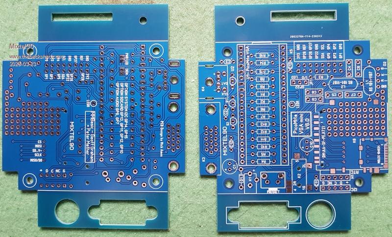 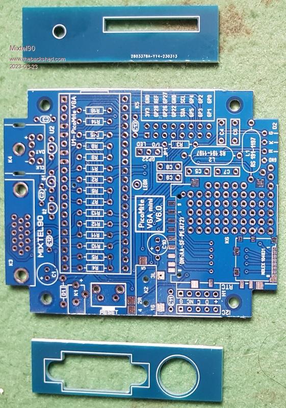 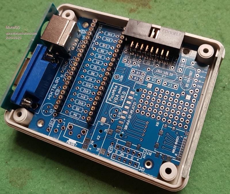 All the holes seem to line up. I've tried a Pico in it and I *think* it's just about low enough now to be able to cut a slot for the USB plug. This is using turned pin connetors instead of the usual headers. I've not got a standard SD socket to try it with. If the slot is a bit out it will just have to be filed down a bit. :) The board is just a tiny bit tight in the box. I'll probably take 0.5mm or so off just to ease things. The cut line isn't usually absolutely bang on when you use the score & nap in the vise system. It's pretty good though. Incidentally, I too had JLPCB contact me about "the hole". I tried to explain that they should keep the hole but get rid of the adjacent pad if it was too close. Eventually she decided that it would be ok as long as the hole wasn't PTH. Anyway, it's come with both the hole and the pad, with the hole non-PTH and it seems to be ideal. They are very good indeed! Mick Zilog Inside! nascom.info for Nascom & Gemini Preliminary MMBasic docs & my PCB designs |
||||
| Mixtel90 Guru Joined: 05/10/2019 Location: United KingdomPosts: 7832 |
I've found a couple of errors so far. Neither too serious. One end of C13 isn't accessible - it's underneath the box header. It can go underneath though, it's only a decoupler and could possibly be omitted. I'd forgotten it was a box header when I put C13 there as an afterthought. The two-way link for GP22 has holes that are too small for a male pin header. I've made this mistake before and didn't learn from that! Some female header and a simple solid core wire link is fine. It's not as if it's something that will be changed much, I don't think. The outer edge of the box header *does* project over the edge of the PCB but it won't stop the PCB from going into the case as a slot has to be cut for it anyway or it can't be used. :) EDIT: This particular uSD card socket isn't good in this particular position in this box. The inserted card doesn't project far enough for it to be pulled out unless you have long nails to catch into the little ridge on top. It *is* usable with that proviso. Mind you, I only included the uSD card so that I could practice soldering them as you can always use a uSD adaptor with the standard SD card socket. Unfortunately I've not got a standard socket so the prototype will have uSD. Well, one of them will anyway. :) Edited 2023-03-24 02:07 by Mixtel90 Mick Zilog Inside! nascom.info for Nascom & Gemini Preliminary MMBasic docs & my PCB designs |
||||
| phil99 Guru Joined: 11/02/2018 Location: AustraliaPosts: 2593 |
" The inserted card doesn't project far enough for it to be pulled out" You could bevel the edges of the slot to get a bit more grip. |
||||
| Mixtel90 Guru Joined: 05/10/2019 Location: United KingdomPosts: 7832 |
Oh, it's easy enough. That's up to the individual though. Personally I don't need a bevel. You could file a semicircular notch below the card but there's not a lot of space for one. This thing is pretty customizable. The "standard" bits are the VGA & PS2 sockets. Probably the IO port too and the power socket for sheer luxury.. Everything else is optional. I suppose you could even build a specialzed display point using only the VGA and power socket and with a HC-12 receiving data to control it from somewhere else. Incidentally, has anyone else noticed that you can use the same pins that the VGA uses to drice a (non-touch) LCD display for a non-VGA PicoMite? You shouldn't connect it via the VGA connector, of course, as you'd be putting non-compatible signals on the pins. I've got some of the stuff on the board now, but I'm searching for my bag of plastic boxes! I know I have a few left somewhere... I don't want to take construction much further as I'm at the point where I need to notch the bottom half of the case. It gets a bit more awkward when there is stuff that's preventing you marking the top surface of the board on the inside of the case so that slots can be cut to the correct depth. EDIT: I've found my boxes! A lot more PCB construction has taken place. A few more slight gotchas: C2 is too tight for a 1uF polybox cap. As I've nothing closer I'm using 100nF as it's relatively close to C1 anyway and I'm not after ideal noise performance from the regulator. C3 won't fit either - it's too close to the PS2 socket. However, the regulator spec says a minimum of 1uF and the reg is feeding into VSYS - which isn't far away and has 47uF on-board. Once again I've put in 100nF to help with the high frequency mush. ANOTHER EDIT: I now have a more-or-less working prototype. SD card and RTC aren't working. The former I can understand as I've probably got bad SMD soldering. The latter I'm not sure about - needs more investigation. All the case holes have worked out rather well, including one for the USB connector. Reset is a little "insert pointy object" hole. Maybe more pics later. YET ANOTHER EDIT: Bad RTC was a dead module. Some reflow work fixed the uSD card socket. Sound is noisy (as expected) but it's working ok. I've done the mod that uses the front panel red LED as heartbeat and it's ok. The on-board green still lights, but only just. The front panel green LED works properly when controlled by GP22. Audio will drive 32R headphones up to "too loud for me" levels. -------------------------------------------- I'm going to update the PCB to version 1.2, taking the above points into consideration. Most of this is done now. I'll update the construction pack soon, as I feel i should clear up some things in the manual too. I'm happy with it, and the current PCB can be used perfectly well if you already have some on order. . Edited 2023-03-25 07:07 by Mixtel90 Mick Zilog Inside! nascom.info for Nascom & Gemini Preliminary MMBasic docs & my PCB designs |
||||
| Mixtel90 Guru Joined: 05/10/2019 Location: United KingdomPosts: 7832 |
Ta Da! 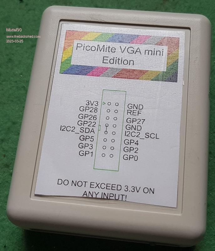 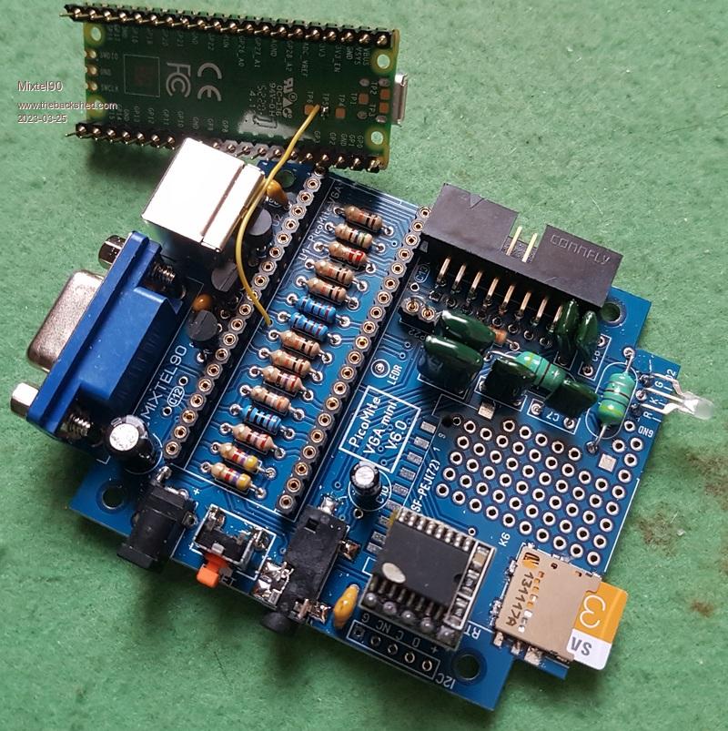 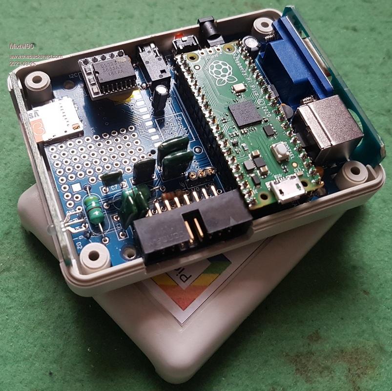 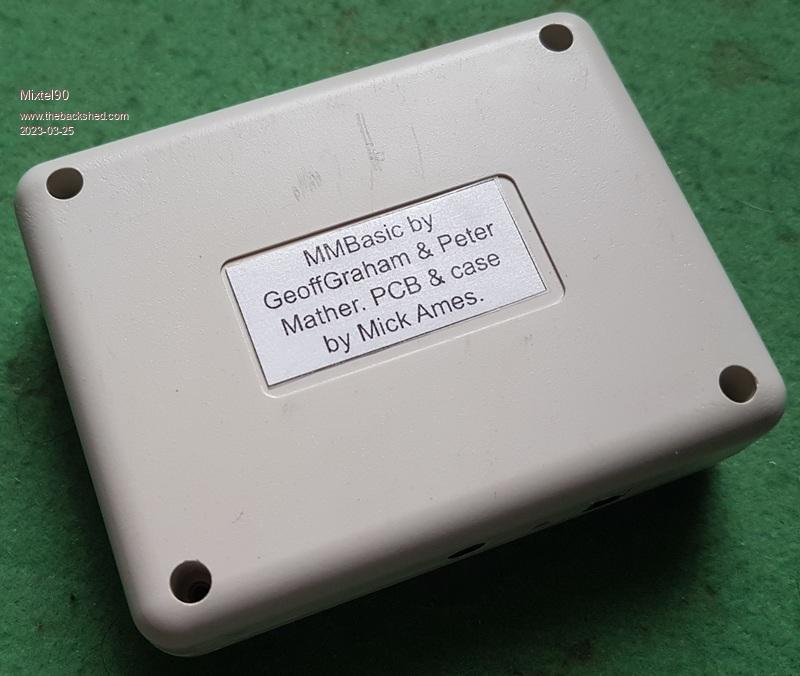 There are one or two "deliberate" mistakes, of course, but operationally it's good, even if the casework leaves a little to be desired! :) I'm just going to start updating the manual. . Mick Zilog Inside! nascom.info for Nascom & Gemini Preliminary MMBasic docs & my PCB designs |
||||
| PilotPirx Regular Member Joined: 03/11/2020 Location: GermanyPosts: 99 |
Hi Mixtel90, the yellow wire goes from ? to ? |
||||
| Mixtel90 Guru Joined: 05/10/2019 Location: United KingdomPosts: 7832 |
From TP5 on the Pico to LEDR on the PCB. It puts the red LED on the PCB in parallel with the green LED on the Pico. The red LED has a lower Vf than the green one so the green one is starved of voltage and virtually goes out, while the red one lights instead. It brings the "heartbeat" to a red LED on the front. Obviously, you can switch "heartbeat" off and control it via GP25. Edited 2023-03-27 17:30 by Mixtel90 Mick Zilog Inside! nascom.info for Nascom & Gemini Preliminary MMBasic docs & my PCB designs |
||||
| Volhout Guru Joined: 05/03/2018 Location: NetherlandsPosts: 5036 |
Beautifull Mick !!! The bottom sticker is the finishing touch ! This would be a nice kit. Guess you are not going to provide kits ? Volhout Edited 2023-03-27 17:33 by Volhout PicomiteVGA PETSCII ROBOTS |
||||
| Mixtel90 Guru Joined: 05/10/2019 Location: United KingdomPosts: 7832 |
I don't know. The idea has its appeal. Postal costs are always the issue. I'd also considered selling the PCBs ready-built, for those with no soldering skills, but I haven't got the time nor the inclination to do the casework. It's quite fiddly. The bits are mostly easy enough to get, but a "part kit" consisting of the PCB, SD, VGA & audio sockets might be one solution. I'm going to include the stickers as a PDF with the manual. :) Mick Zilog Inside! nascom.info for Nascom & Gemini Preliminary MMBasic docs & my PCB designs |
||||
| Mixtel90 Guru Joined: 05/10/2019 Location: United KingdomPosts: 7832 |
I've just updated the Construction Pack. Niggles on PCB sorted out. Revisions to Manual Slight revision to circuit. Pretty drawing for labels. :) Have fun... . Mick Zilog Inside! nascom.info for Nascom & Gemini Preliminary MMBasic docs & my PCB designs |
||||
| Mixtel90 Guru Joined: 05/10/2019 Location: United KingdomPosts: 7832 |
An alternative set of Gerbers has been added to the Construction Pack. (from Readme.txt file) If you don't fancy soldering a micro SD card socket then this may not be for you (unless you don't want SD storage at all). Mick Zilog Inside! nascom.info for Nascom & Gemini Preliminary MMBasic docs & my PCB designs |
||||
| lizby Guru Joined: 17/05/2016 Location: United StatesPosts: 3349 |
Mick--for the PicoMiteVGA Mini V6, I soldered on nothing but the headers for the Pico, the VGA and keyboard connectors, and the resistors. VGA works but my keyboard doesn't. This is a thrift store PS/2 keyboard which my wife bought, not known to work. Should there be anything else needed to make it work?  (Nice little board, by the way--thanks.) By the way, are there any good demo programs available for VGA (non-game in particular, although vegipete's Crate-away or ChemiChaos would be about my speed). PicoMite, Armmite F4, SensorKits, MMBasic Hardware, Games, etc. on fruitoftheshed |
||||
| Mixtel90 Guru Joined: 05/10/2019 Location: United KingdomPosts: 7832 |
You definitely need the MOSFETs (Q1 and Q2) for the level shifter. The keyboard is powered at 5V so those are always required. Glad you like the board. :) I know it works because mine is working nicely and it's the same version. Mick Zilog Inside! nascom.info for Nascom & Gemini Preliminary MMBasic docs & my PCB designs |
||||
| lizby Guru Joined: 17/05/2016 Location: United StatesPosts: 3349 |
No joy with 2 BS170s turned opposite. Heading to the thrift store later today. PicoMite, Armmite F4, SensorKits, MMBasic Hardware, Games, etc. on fruitoftheshed |
||||
| matherp Guru Joined: 11/12/2012 Location: United KingdomPosts: 10207 |
And the four resistors |
||||
| The Back Shed's forum code is written, and hosted, in Australia. | © JAQ Software 2025 |
