
|
|
Forum Index : Microcontroller and PC projects : Design #3 - PicoMite VGA mini
| Author | Message | ||||
| thwill Guru Joined: 16/09/2019 Location: United KingdomPosts: 3846 |
This is a different VGA connector from the PicoGAME VGA isn't it ? In that case I used these: https://www.aliexpress.com/item/1005003798059447.html which look more like the Farnell part. Best wishes, Tom Game*Mite, CMM2 Welcome Tape, Creaky old text adventures |
||||
| Mixtel90 Guru Joined: 05/10/2019 Location: United KingdomPosts: 5731 |
It is, yeah. I used the more (UK) standard one for PicoGAME but I haven't got room for it on the tight builds. Mick Zilog Inside! nascom.info for Nascom & Gemini Preliminary MMBasic docs & my PCB designs |
||||
| atmega8 Guru Joined: 19/11/2013 Location: GermanyPosts: 712 |
Mick, is your construction Pach available, did. I miss this Information? |
||||
| Mixtel90 Guru Joined: 05/10/2019 Location: United KingdomPosts: 5731 |
I couldn't post it to the forum. I mentioned this in my first post this morning. :) Edited 2023-03-11 08:00 by Mixtel90 Mick Zilog Inside! nascom.info for Nascom & Gemini Preliminary MMBasic docs & my PCB designs |
||||
| atmega8 Guru Joined: 19/11/2013 Location: GermanyPosts: 712 |
Hi, sorry, but what/where is „the link in my sig“?. Ok, found it!!!! Edited 2023-03-11 08:29 by atmega8 |
||||
| Mixtel90 Guru Joined: 05/10/2019 Location: United KingdomPosts: 5731 |
I know this has hardly got off the ground yet, but I've had an idea for a couple of "Pods". These sit adjacent to the right-hand side and have a PCB-mounted connector that plugs into the mini. They fit into the same case so are part of the "family". Only one can be fitted at once, purely because of the number of IO pins available. The experimenter's pod (for want of a better name) has two rows of 10 SIL sockets that poke out through the top. These are more or less the pins of the connector but rearranged into the PicoMite pattern. There is also a power Off/On switch.The 5V supply is fed into this pod and a flying lead then powers the mini, so the 5V supply is intercepted. The mini is continuously powered. A MOSFET is used as a switch, switching the 5V supply to both a pin on one of the SIL sockets and an internal 3V3 regulator - this is the 3V3 supply to the SIL sockets. The power switch turns the MOSFET off, thus disconnecting both 5V and 3V3 supplies. The 3V3 supply from the mini is used as an interlock, neither of the Pod supplies can be applied unless the mini is powered up first. This prevents any back feed into the mini's GPIO pins. The gaming pod (for want of yet another name) has a DB9 connector on the front for any of the joysticks/controllers usable on Port A of the PicoGAME. A second DB9 on the rear allows connection of a second controller (not joysticks - there's not enough IO. It could be fiddled but it's not worth the extra work). At this stage the software drivers wouldn't be compatible with those of the PicoGAME as some of the IO pins would have to be different. Does anyone think these ideas are worth pursuing? Mick Zilog Inside! nascom.info for Nascom & Gemini Preliminary MMBasic docs & my PCB designs |
||||
| thwill Guru Joined: 16/09/2019 Location: United KingdomPosts: 3846 |
I can't comment on that  That wouldn't be a problem for my controller library, though I might have to return to the idea of a small file in A:/ to provide a hint as to the controller layout. You can get quite far by "probing" the I/O pins, but I'm concerned about unexpected side-effects such as might happen if you start sending NES clock and latch signals to pins that are attached to some random piece of hardware. Best wishes, Tom Game*Mite, CMM2 Welcome Tape, Creaky old text adventures |
||||
| thwill Guru Joined: 16/09/2019 Location: United KingdomPosts: 3846 |
Could the pod allow for the optional installation of a 4021 shift register and 5 pull-up resistors so that a second Atari joystick is presented as an NES controller? Best wishes, Tom Game*Mite, CMM2 Welcome Tape, Creaky old text adventures |
||||
| Mixtel90 Guru Joined: 05/10/2019 Location: United KingdomPosts: 5731 |
I suppose I *could* make the pods use a 1-wire device on GP22 to identify which is in use, if any. Obviously, it couldn't be used to light an LED then but that's probably not that important if you are using one of these. At the moment (pins on rear may be rearranged): Front 1 - GP0 - Up 2 - GP1 - Down / controller data 3 - GP2 - Left / controller latch 4 - GP3 - Right / controller clock 5 - GP26 6 - GP4 - Fire / controller power 7 - 3V3 8 - GND 9 - GP27 Rear 1 - NC 2 - GP26 - controller data 3 - GP27 - controller latch 4 - GP28 - controller clock 5 - NC 6 - GP4 - 3V3 controller power 7 - NC 8 - GND 9 - NC I've toyed with the idea of putting 330R resistors on all the GP pins in the pod. It would protect against output overloads and make no difference when used as inputs. Same for the experimenter's pod. Mick Zilog Inside! nascom.info for Nascom & Gemini Preliminary MMBasic docs & my PCB designs |
||||
| Mixtel90 Guru Joined: 05/10/2019 Location: United KingdomPosts: 5731 |
That's an idea..... :) Of course, a longer shift register would allow both joysticks and their fire buttons to be read in a single process. Hmmm.... Edited 2023-03-11 20:23 by Mixtel90 Mick Zilog Inside! nascom.info for Nascom & Gemini Preliminary MMBasic docs & my PCB designs |
||||
| Geoffg Guru Joined: 06/06/2011 Location: AustraliaPosts: 3165 |
Mick. Do you have a photo of the final thing built? for the manual. Geoff Geoff Graham - http://geoffg.net |
||||
| thwill Guru Joined: 16/09/2019 Location: United KingdomPosts: 3846 |
TBH it wouldn't help me, I'd just end up having to read the longer shift register twice. Sure my controller library could be adapted to cache the results of a single "read", but for maintenance and sanity it's easiest to adopt a lowest common denominator approach where the controllers are handled completely independently. There's also the issue that even the most ardent horse hater realises when the dead horse has had enough - I won't stop amusing myself with the PicoMite/CMM2 as a retro computing platform but it appears that the niche of retro computing fans not using the original hardware or an emulator would rather use a "real" 8-bit processor even if for video/sound/IO it is then tethered to an FPGA which could easily emulate the aforementioned processor (and more).Best wishes, Tom Edited 2023-03-11 21:03 by thwill Game*Mite, CMM2 Welcome Tape, Creaky old text adventures |
||||
PilotPirx Regular Member Joined: 03/11/2020 Location: GermanyPosts: 66 |
I got an error Message from JLCPCB. They want to remove a hole: 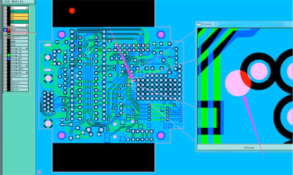 It seems to be a mistake. I have allowed them to remove the hole. |
||||
| Mixtel90 Guru Joined: 05/10/2019 Location: United KingdomPosts: 5731 |
I'd have taken the pad off instead. That hole is a locator for the SD card. The pad is merely a support for my experiment to fit a HC-12 inside the case. I've just got the message too. Here's my reply: To be honest, I had my doubts about that anyway. The holes are too close together. As the HC-12 can't be fitted with the standard SD card I can always do something with that locator hole. I might turn it into a pad and make it dual purpose. Edited 2023-03-11 22:23 by Mixtel90 Mick Zilog Inside! nascom.info for Nascom & Gemini Preliminary MMBasic docs & my PCB designs |
||||
| Mixtel90 Guru Joined: 05/10/2019 Location: United KingdomPosts: 5731 |
I will have when I've built one, Geoff. :) I have some PCBs on order. Mick Zilog Inside! nascom.info for Nascom & Gemini Preliminary MMBasic docs & my PCB designs |
||||
| Mixtel90 Guru Joined: 05/10/2019 Location: United KingdomPosts: 5731 |
I'm not as apprehensive about soldering a micro SD card socket on these now. I've just done one on a PicoGAME VGA 2.0 and I think it's OK (there's nothing else on the board). It's fiddly and involves syringes of flux and solder paste with a heat gun, but it's doable. The full size SD card socket is a lot easier! Mick Zilog Inside! nascom.info for Nascom & Gemini Preliminary MMBasic docs & my PCB designs |
||||
| JohnS Guru Joined: 18/11/2011 Location: United KingdomPosts: 3659 |
It'll work without the uSD socket - right? John |
||||
| Mixtel90 Guru Joined: 05/10/2019 Location: United KingdomPosts: 5731 |
Oh yeah, you just lose the sea of holes. It'll work without either SD card socket if you are happy with just drive A:. The standard size is remarkably easy to do. Just a flux pen, ordinary solder and a pointy iron tip. Mick Zilog Inside! nascom.info for Nascom & Gemini Preliminary MMBasic docs & my PCB designs |
||||
| Mixtel90 Guru Joined: 05/10/2019 Location: United KingdomPosts: 5731 |
@Tom Yes, done it. Only Up, Down, Left, Right & Fire (button A). You can't use a controller on the rear socket now. GP27 - Latch GP26 - Clock GP5 - Data The rear Joystick is a conventional Atari sort with a single fire button. It can only be used if the front socket is either an Atari switched one or a controller. I pinched the ADC inputs as otherwise I'd have needed GP22 and that might not be available. Another approach would have been to arrange the 8 NES bits to give Up, Down, Left & Right for both joysticks and wire the fire buttons to separate inputs. That would be interesting as they could be interrupts. Edited 2023-03-12 03:47 by Mixtel90 Mick Zilog Inside! nascom.info for Nascom & Gemini Preliminary MMBasic docs & my PCB designs |
||||
| thwill Guru Joined: 16/09/2019 Location: United KingdomPosts: 3846 |
Not that I'm trying to keep you our of mischief or anything, but how about some male headers and shunts to control whether to use an NES controller (with the 4021 in the controller) or the Atari joystick (with the 4021 on the PCB) ? Though you may want to give it all a miss since if I build this thing at all it will be after mooching PCBs from you and only so I can add the drivers to my controller code  . .Best wishes, Tom Game*Mite, CMM2 Welcome Tape, Creaky old text adventures |
||||
