
|
|
Forum Index : Microcontroller and PC projects : PicoMite: can we explain/fix "ticking" when using PLAY SOUND
| Author | Message | ||||
| matherp Guru Joined: 11/12/2012 Location: United KingdomPosts: 10195 |
Try something for me Play sound 1,b,q,523,20 Do Play sound 1,b,s,523,20 Pause 400 Play sound 1,b,s,423,20 Pause 400 Loop |
||||
| thwill Guru Joined: 16/09/2019 Location: United KingdomPosts: 4301 |
Quiet as the grave  . .Edited 2023-03-21 02:37 by thwill MMBasic for Linux, Game*Mite, CMM2 Welcome Tape, Creaky old text adventures |
||||
| thwill Guru Joined: 16/09/2019 Location: United KingdomPosts: 4301 |
Are the previous betas still available for download, perhaps it was already "broken" (at least for me) since 5.07.06 ? MMBasic for Linux, Game*Mite, CMM2 Welcome Tape, Creaky old text adventures |
||||
| matherp Guru Joined: 11/12/2012 Location: United KingdomPosts: 10195 |
One last try PicoMite.zip |
||||
| thwill Guru Joined: 16/09/2019 Location: United KingdomPosts: 4301 |
 Works for my test example, you're a star! I'll try it with real thing later this evening. Thanks Peter, in this case a firmware fix was more than I had hoped for. Best wishes, Tom MMBasic for Linux, Game*Mite, CMM2 Welcome Tape, Creaky old text adventures |
||||
| thwill Guru Joined: 16/09/2019 Location: United KingdomPosts: 4301 |
Looks like it may still tick if playing sound on multiple channels  and, hopefully coincidentally, I appear to have killed my IL9341, it no longer updates properly and, hopefully coincidentally, I appear to have killed my IL9341, it no longer updates properly  . .Best wishes, Tom MMBasic for Linux, Game*Mite, CMM2 Welcome Tape, Creaky old text adventures |
||||
| Pluto Guru Joined: 09/06/2017 Location: FinlandPosts: 375 |
How can a pico kill an ILI9341? I have used 9341s for years with micromites and picomites. Connections mostly with wires; sometimes wrong connected  . I never managed to kill any, except for a mechanical damage of the touch screen. I have found them very reliable. Ordered from several Ali Express suppliers. . I never managed to kill any, except for a mechanical damage of the touch screen. I have found them very reliable. Ordered from several Ali Express suppliers. |
||||
| thwill Guru Joined: 16/09/2019 Location: United KingdomPosts: 4301 |
I think most likely a monkey who has become blase about ESD protection (i.e. uses none) killed it, though I suppose it's possible there is a poor solder joint on it somewhere, I'll run the soldering iron over it but I'm dubious. Don't know if it is relevant but it was an old no-touch v1.1 module. Best wishes, Tom Edited 2023-03-21 06:01 by thwill MMBasic for Linux, Game*Mite, CMM2 Welcome Tape, Creaky old text adventures |
||||
| Volhout Guru Joined: 05/03/2018 Location: NetherlandsPosts: 5030 |
Tom, Try Your THE ENTERTAINER program. Peter dan Try this too. Volhout PicomiteVGA PETSCII ROBOTS |
||||
| thwill Guru Joined: 16/09/2019 Location: United KingdomPosts: 4301 |
I've had a closer look and it is fixed even for multiple channels, what still ticks is doing this: Do Play Sound 1,b,s,400 Pause 200 Play Sound 1,b,s,400,0 Pause 200 Loop Which is effectively how my music engine was handling rests, i.e. by playing notes with volume 0. I could stop doing this, but it would require slightly more code to be executed by my music engine interrupt handler, I don't suppose you'd consider changing the firmware such that: Play Sound 1,b,anything,anything,0 is handled the same as: Play Sound 1,b,o Even if not then thanks for fixing the principle problem. Best wishes, Tom Edited 2023-03-21 09:40 by thwill MMBasic for Linux, Game*Mite, CMM2 Welcome Tape, Creaky old text adventures |
||||
| Turbo46 Guru Joined: 24/12/2017 Location: AustraliaPosts: 1638 |
Can I summarise a few points here. - A battery in not a noisy supply source but any logic IC is a noisy load, particularly a microprocessor. Think of all of those internal switch circuits switching on and off at a million miles and hour. Especially switching circuits that have an active pullup and pulldown output, these have the potential to have both the high and low sides to be at least partially 'on' during the switching process. This will cause a spike of current to be drawn from the power supply creating noise on the power supply. Batteries have an internal effective serial resistance (ESR) which means that an increase in current will cause a drop in the output voltage. A microprocessor with thousands of little switching circuits in it will cause a lot of noise on the power supply (like a hiss). An electrolytic across the supply will help flatten out the noise on the power supply but they also have ESR so a 0.1uF will help remove the higher frequencies. Every IC should have a 0.1uF capacitor across the supply as close as possible to it's power supply pins. The display is a potential source of noise also and should at least have a 0.1uF across it's supply. The amplifier is another source of noise and is also affected by it. It should also have an electrolytic and a .01uF across it's supply. - There IS audio at the output of the filter - see the attached diagram: 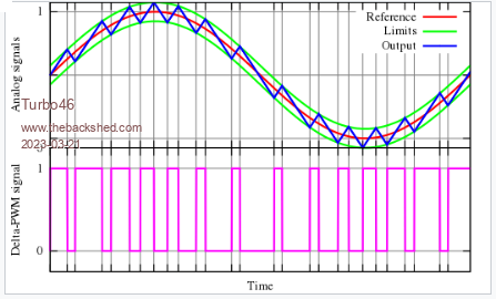 The output is the blue jagged line. The more aggressive the filter is the lower level of 'jaggedness' there will be in the output. This is why I asked Volhout for a two stage filter cutting of a around 5kHz. Notice that there is a DC offset in the audio signal. - The volume control pot for an amplifier must never pass DC. This causes a scratchy noise particularly when it is turned. See the attached circuit: 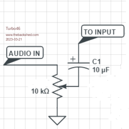 The capacitor needs to be reasonably large because it needs to pass the audio signal frequencies recovered from the PWM. - If the remnants of the PWM signal pass through the amplifier, they should not be reproduced by the speaker. Even if they were, you would not hear them unless you are a bat.  Bill Edited 2023-03-21 10:21 by Turbo46 Keep safe. Live long and prosper. |
||||
| Mixtel90 Guru Joined: 05/10/2019 Location: United KingdomPosts: 7823 |
Just to follow that up... The remains of the PWM carrier signal are at about 40,000 Hz. That's darn high (as your ears age they will tend to fall in response from around 20,000 Hz when you are young to around 4000 Hz or lower. You aren't going to hear 40,000 Hz, but most amplifiers will handle it to some extent and with modern output stages it will get to the speakers. Speakers are horrible, inefficient converters of current to air movement. A lot of that current goes into warming the voice coil up. The speaker can't reproduce 40,000 Hz, but that doesn't mean that any output at that frequency doesn't contribute to that heating effect. In fact, tweeters are built with very light coils of very fine wire that have difficulty in getting rid of heat. (Some of you may have heard of Ferrofluid voice coils. In these there the voice coil is surrounded by a fluid that is held in place by the magnetic field. This fluid is to help conduct heat away.). This is why we need to get rid of as much 40,000 Hz content as possible - it can burn out the coils of tweeters and you can't hear the damage happening until it's too late. Having 40,000 Hz at the speaker isn't necessarily harmful, but the level of it is the problem. Coming out of the PicoMite the 40,000 Hz is at 3.3V. If you drop that with resistors then you drop the actual audio by the same amount. You want to keep the audio yet reduce the 40,000 Hz content. The idea of putting a filter after the PWM signal is to remove all frequencies from above those that are useful to us. (It's a "low pass" filter.) That's above 20,000 Hz at most. We want to keep as much of the frequency range below that as possible. Ideally we would hear up to 20,000 Hz and hear nothing at 21,000 Hz, but filters are not like that, they have sloping characteristics. The steepness of the slope is dependent on how complex you make the filter, basically. The original audio filter from the manuals used a single resistor and capacitor for the PWM stage (anything after that makes no difference to the response). That hardly reduces the 40,000 Hz signal at all. Adding a second stage will help a tiny bit, but in order to get a low output at 40,000 Hz you may have to sacrifice everything above about 500 H as the slope is far to shallow. IIRC Volhout tried up to about five of these RC stages and the filter was still pretty ineffective. Volhout's filter using an inductor tuned by a capacitor is much steeper and can give very low levels of 40,000 Hz while still sounding very good (especially if you have ageing lug-'oles!). His op-amp design is better still, but is even more complex (remember that filters improve as they get more complex?). But what about listening on headphones? The power required to headphones is much, much lower than that needed to move a speaker cone, hence the heating effect of the 40,000 Hz signal is much, much less. Mick Zilog Inside! nascom.info for Nascom & Gemini Preliminary MMBasic docs & my PCB designs |
||||
| matherp Guru Joined: 11/12/2012 Location: United KingdomPosts: 10195 |
Tom Try this PicoMite (2).zip |
||||
| Turbo46 Guru Joined: 24/12/2017 Location: AustraliaPosts: 1638 |
Mick, While I agree with much of what you say I think you may be over stating the effects of the 40kHz on the output. I guess a notch filter centred at the offending 40kHz would be best if that were incorporate into a low pass filter circuit but do we really need to aim for HiFi? Bear in mind that for Tom's use he is not feeding the signal though a HiFi amplifier to a set of HiFi speakers but to a Micky Mouse tiny speaker. The maximum frequency of his music is below 5kHz and that is why I suggested a two stage RC filter with a cut-off at about 5kHz. A properly designed two stage RC filter will have twice the roll-off rate of a single stage filter not 'just a little bit'. Where that leaves the PWM signal residue of 40kHz, I don't know but I don't believe it will affect Tom's project. Bill Keep safe. Live long and prosper. |
||||
| thwill Guru Joined: 16/09/2019 Location: United KingdomPosts: 4301 |
Thanks. Should I be testing this, or the version that you posted later in the 5.07.07 betas thread (which you may want to convert into a proper link) ? Best wishes, Tom MMBasic for Linux, Game*Mite, CMM2 Welcome Tape, Creaky old text adventures |
||||
| matherp Guru Joined: 11/12/2012 Location: United KingdomPosts: 10195 |
Same |
||||
| thwill Guru Joined: 16/09/2019 Location: United KingdomPosts: 4301 |
Thank you very much Peter, I can confirm that b28 downloaded from the other thread fixes the "clicking zero-volume rests" issue  . .Also thank you Bill, Mick, et al., for going the extra mile with your educational comments. However, before we start discussing filters again I need to: 1. Add the capacitor confetti (if confetti were shaped like small dustbins) to deal with the electrical noise. 2. Find out exactly how much perfboard real-estate my Mk2 prototype (100mm x 100mm instead of the MkI's 90mm x 150mm) has for the audio components. Bill this is all your fault, I was happy with raw PWM driving two 16ohm buzzers, two transistors and 4 resistors - who needs 4 channel sound anyway ? Best wishes, Tom MMBasic for Linux, Game*Mite, CMM2 Welcome Tape, Creaky old text adventures |
||||
| Mixtel90 Guru Joined: 05/10/2019 Location: United KingdomPosts: 7823 |
A notch filter would indeed do it, Bill, but you are over-complicating things as there's no need to pass anything above it. A low pass is perfectly adequate and simpler. It still needs to be steep. Note that a notch filter would only significantly reduce the level of the fundamental. You still need to get rid of 80kHz and 120kHz etc. You may think that your amp won't transmit RF but many modern class D ones are quite capable of doing so - and most have inductive filters in the speaker leads because of that (they remove the switching frequency in theory). I realise that what I said is really for those feeding "proper" amplification and speakers, but I was trying to describe why we need a filter at all and why, when we do, it's important to know how to do it. It doesn't apply to a telephone earpiece "speaker", just as it doesn't apply to most earphones, but it does apply to a 3.5mm stereo jack socket on a board design for others to build as you have no control over what's going to be plugged into it. You are starting off with a high level of 40kHz. Whatever comes out of the filter is going to be amplified, that includes the 40kHz. Unless you can get that very low relative to the signal level it will still be appreciable. One or two stages of RC filtering won't cut it if you feed a 1W amplifier, never mind anything bigger. The aim is to get the output so that the audio is plenty loud enough and the 40kHz level isn't important. It doesn't have to be non-existent, but it does need to be low level at normal listening volumes. Mick Zilog Inside! nascom.info for Nascom & Gemini Preliminary MMBasic docs & my PCB designs |
||||
| Mixtel90 Guru Joined: 05/10/2019 Location: United KingdomPosts: 7823 |
I've been looking at a design for a simple mono amplifier based on a LM358 dual op amp. I don't know if that would be of interest, Tom. It may be a bit bigger than your PAM module though. I've not built this, it's just a design. For those of a technical mind: Both op amps are wired as inverting, with their non-inverting inputs connected to a half-supply virtual ground. All resistors are 10k. The speaker is connected between the outputs. One input is the signal input, via a capacitor. The other input is connected to the input amplifier's output. Thus the outputs will normally sit at half supply voltage and the voltage on the speaker is approximately twice the supply voltage. The LM358 should be great for this as it's cheap, rugged and will work down to 3V single supply. You could build this as stereo, using a LM324 (same op amps but four in a DIL14 package rather than two in a DIL8). You can share the virtual ground (two resistors and one capacitor) as there's no load on it. Mick Zilog Inside! nascom.info for Nascom & Gemini Preliminary MMBasic docs & my PCB designs |
||||
| Volhout Guru Joined: 05/03/2018 Location: NetherlandsPosts: 5030 |
The LM358 can handle only few mA. It is not suited for buzzers or headphones or earplugs. Its is however very usefull for classic 600 ohm headphones. The LM358 (and alikes LM324) have cross-over distortion (they are nice general purpose opamps, but not really good at audio, except when you know how to compensate for it's shortcommings). Volhout Edited 2023-03-21 22:40 by Volhout PicomiteVGA PETSCII ROBOTS |
||||
| The Back Shed's forum code is written, and hosted, in Australia. | © JAQ Software 2025 |
