
|
|
Forum Index : Microcontroller and PC projects : PicoMite: driving a small speaker
| Author | Message | ||||
| phil99 Guru Joined: 11/02/2018 Location: AustraliaPosts: 1813 |
"Also am I to understand that the PAM8403 design is falling out of favour" Using Peter's "M" parameter and Mozzie's circuit the PAM8302 is back in the game! The differential PWM signals are filtered and sent to the PAM8302 differential inputs as per Volhout's circuit above. Edit Tested differential PWM on a LM386 That too is dead quiet when there is no sound playing. Edited 2023-04-04 09:42 by phil99 |
||||
| mozzie Regular Member Joined: 15/06/2020 Location: AustraliaPosts: 68 |
G'day Tom, After some further tinkering I'm sorry to say that the PAM8403 is not a great match to this circuit, the input is non-differential so doesn't allow the new magic to work  I did try to feed the audio across the inputs (L/R) and speaker across the outputs (L+/R+), but whilst it does make sound, it still makes a lot of odd noises, pretty sure its heterodyning due to the oscillators operating at different frequencies between channels. Someone else here might have a better solution. You could also use an op-amp buffer to drive it, that would work fine.  See below for basic circuit with PAM8302:  This uses what was handy and could be optimised further, most values non-critical. Volume control as attenuator to keep signal impedance balanced. As suggested by others, will also work with LM386(x2 bridge) TDA2822 etc LM4871 possibly not as its a bridge amp internally, cant feed differential signal. Volhout, that circuit will add some much needed bottom end although Tom is going to have to try different speakers and amounts of bass boost to find a compromise, the speaker is going to run out of "Talent" at low frequency pretty quick. Regards, Lyle. |
||||
| mozzie Regular Member Joined: 15/06/2020 Location: AustraliaPosts: 68 |
Onto Speakers: If the TomBoy project is going to be fitted with a bottom cover or base plate, then possibly this type of speaker glued onto it would provide a good solution, this is the test speaker here: https://www.jaycar.com.au/40mm-all-purpose-replacement-speaker/p/AS3004  These are 40mm dia and approx 10mm thick, mounted to a baffle they provide a surprising amount of output.  Regards, Lyle. |
||||
| Mixtel90 Guru Joined: 05/10/2019 Location: United KingdomPosts: 5771 |
These speakers are not intended to be used without a baffle of some sort. The loop distance through the air from the front to the back is so short that it takes no time for the air to get round. This removes all pretense of bass - and even a lot of the mid range. Sometimes they are push-fitted into a rubber (or similar) moulding that is fastened into a case (rather like a soft, large grommet). Holding them down and adding a few blobs of hot glue round the edges also works. :) Just keep it out of any vent holes on the rear. Mick Zilog Inside! nascom.info for Nascom & Gemini Preliminary MMBasic docs & my PCB designs |
||||
| thwill Guru Joined: 16/09/2019 Location: United KingdomPosts: 3865 |
G'day folks, Thanks. In the great state of California everything can give you cancer. I suspect they tested one that had leaded solder in its construction. I find the secret with electronic devices is to NOT EAT THEM  . .Honestly I suspect that is going to be out of the question when it comes to small speakers (I don't hink I'm going to fit a 40mm one Lyle). Middle-C is 261 Hz and I would guess (and it's an almost complete guess) the spec for most tiny speakers starts higher than that. I read that mobile phones rely on very careful choice and enclosure design that's going to be beyond a hobbyist creation. I also suspect that unless the Tomboy is provided as a kit those handful (if any) who build it will just be slapping in whatever small speaker they have to hand. Quality just needs to be (barely) adequate and without electronic "noise". Still part of the plan. Am I correct that you would only require one TDA2822 ? That looks like a cheap/easily available DIP package that would be preferable to a "module". Does anyone know if it requires significant support components ? - I know I could look at the spec. sheet, but ... lazy  . .Can someone confirm that the latest posts / schematics are all still using the Pico's onboard DAC and not Peter's new support for the external DAC ? Best wishes, Tom Game*Mite, CMM2 Welcome Tape, Creaky old text adventures |
||||
| Volhout Guru Joined: 05/03/2018 Location: NetherlandsPosts: 3591 |
@Tom, I haven't seen the DAC yet. I know a DAC will solve some/many of the issues we have (noise, 44kHz, sample rate conversion(*)). But it is another chip to add. The DAC will not drive a speaker. So you need the DAC and you need the amplifier. MCP4822 + TDA2822 something alike... Volhout (*) sample rate conversion when the input signal (playing a file) is not 44.1kHz, but 8kHz, 16kHz or 48kHz samples. You need to "calculate" values before sending them to the PWM. For a DAC it is simple: just write it to the DAC in the speed the data is sampled. Edited 2023-04-04 19:26 by Volhout PicomiteVGA PETSCII ROBOTS |
||||
| matherp Guru Joined: 11/12/2012 Location: United KingdomPosts: 8607 |
That's not how it works. When playing a file using PWM the frequency changes to the nearest multiple of the required frequency greater than 44100 at 126MHz and faster at higher clock speeds. if(Option.AUDIO_L){ // If PWM and not DAC audiorepeat=1; actualrate=mywav.sampleRate; //sample rate from the wav file while(actualrate<PWM_FREQ){ actualrate +=mywav.sampleRate; audiorepeat++; } setrate(actualrate); } else { //DAC setrate(mywav.sampleRate); } |
||||
| Turbo46 Guru Joined: 24/12/2017 Location: AustraliaPosts: 1595 |
The latest developments in the sound commands have left me behind but using a DAC or PWM to produce sounds (wave shapes) are two different methods. You are using PWM to produce the sounds, that has nothing to do with the DAC. The PWM method modulates the mark-space ratio of the PWM signal which must be de-modulated to restore the audio by using a filter or integrator. The DAC (Digital to Analogue Converter) method uses a lookup table or calculations to produce an analogue signal which is updated rapidly to produce the desired analogue signal. You can see the steps in one of Peter's earlier 'scope traces. Bill Keep safe. Live long and prosper. |
||||
| matherp Guru Joined: 11/12/2012 Location: United KingdomPosts: 8607 |
The two are basically identical other than the PWM needing a low pass filter These are the two routines that set the output. The software uses one or the other depending on the options set by using the function pointer AudioOutput. Everything else is identical. This mechanism easily allows other types of DAC to be used with a simple additional routine and also allows the output function to be substituted by a CSUB void __not_in_flash_func(DefaultAudio)(uint16_t left, uint16_t right){ pwm_set_both_levels(AUDIO_SLICE,(left*AUDIO_WRAP)>>12,(right*AUDIO_WRAP)>>12); } void __not_in_flash_func(SPIAudio)(uint16_t left, uint16_t right){ uint16_t l=0x7000 | left, r=0xF000 | right; gpio_put(AUDIO_CS_PIN,GPIO_PIN_RESET); spi_write16_blocking((AUDIO_SPI==1 ? spi0 : spi1),&r,1); gpio_put(AUDIO_CS_PIN,GPIO_PIN_SET); gpio_put(AUDIO_CS_PIN,GPIO_PIN_RESET); spi_write16_blocking((AUDIO_SPI==1 ? spi0 : spi1),&l,1); gpio_put(AUDIO_CS_PIN,GPIO_PIN_SET); } void (*AudioOutput)(uint16_t left, uint16_t right) = (void (*)(uint16_t, uint16_t))DefaultAudio; Edited 2023-04-04 20:26 by matherp |
||||
| Volhout Guru Joined: 05/03/2018 Location: NetherlandsPosts: 3591 |
Hi Peter, Just for my understanding. Is this happening on a per sample basis, or is this a calculated when interpreting the PLAY statement. Per sample basis: a 8kHz sampled file would repeat 1 sample 5x (40kHz), 1 sample 6x (48kHz) alternating. Once: a 8kHz sampled file would repeat each sample 6x (6x8 = 48kHz > 44.1kHz) but play the song at 44.1/48= 90% speed. PicomiteVGA PETSCII ROBOTS |
||||
| matherp Guru Joined: 11/12/2012 Location: United KingdomPosts: 8607 |
It always plays at the correct speed. A 8kHz sample will output 6 identical PWM waves @ 48KHz |
||||
| Volhout Guru Joined: 05/03/2018 Location: NetherlandsPosts: 3591 |
OK, got it. It is playing at 48kHz, not 44.1kHz.... Yes, that should work fine. You do not have the benefit of the 44kHz rejection, since the carrier moves to 48kHz, but that should be fine also. Volhout PicomiteVGA PETSCII ROBOTS |
||||
| mozzie Regular Member Joined: 15/06/2020 Location: AustraliaPosts: 68 |
G'day Tom, Correct, only 1 x TDA2822 required but they have been obsolete in DIP package for a while from legit suppliers so its ALI etc and hope they work.  There is also TDA2822D in SOIC still around if you can find them. This works with the PWM output from the Pico, no DAC required. This is the circuit I am using: 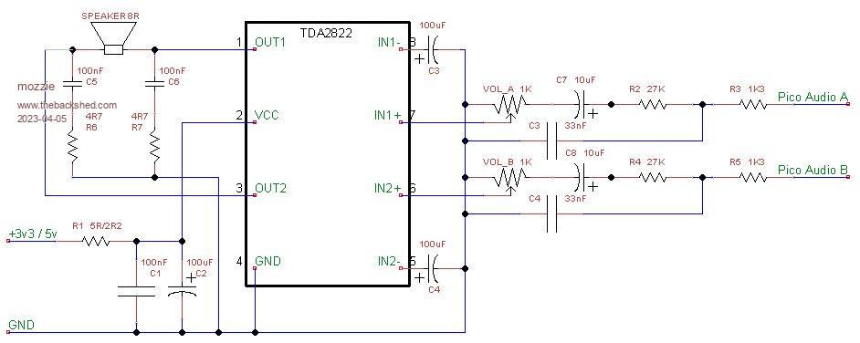 Its a bit messy but that is the layout of the chip... Once again you can play around with different filters etc that others have designed, this was what I had at hand, also requires stereo volume control pot. Regards, Lyle. Edited 2023-04-05 21:40 by mozzie |
||||
| thwill Guru Joined: 16/09/2019 Location: United KingdomPosts: 3865 |
Thanks Lyle, I have the parts for this and the PAM8302 circuit (including Chinesium IC's) but with 20K dual-pot's (not 1K) on the slow boat. I note this circuit has five trash-can capacitors I'd have to find room for, though I suppose the 10uF are available as tantalum beads. Perhaps any Tomboy PCB should just have a sea of holes for the audio and a silk-screen that says "Good Luck!" Best wishes, Tom Edited 2023-04-05 21:43 by thwill Game*Mite, CMM2 Welcome Tape, Creaky old text adventures |
||||
| matherp Guru Joined: 11/12/2012 Location: United KingdomPosts: 8607 |
10uF are available as 1206 smd multi-layer ceramic which are the perfect size to solder across 0.1" pads on stripboard etc. |
||||
| thwill Guru Joined: 16/09/2019 Location: United KingdomPosts: 3865 |
Thanks Peter. Lyle, on the PAM8302A circuit is that the circuit for a PAM IC on its own or for the module ? Best wishes, Tom Game*Mite, CMM2 Welcome Tape, Creaky old text adventures |
||||
| mozzie Regular Member Joined: 15/06/2020 Location: AustraliaPosts: 68 |
Hi Tom, The circuit is for the module, however the input circuit for the TDA2822 is an improvement so I'll update the PAM circuit if required. Perhaps you have the answer on the prototype already, put a header with +V / Audio A / Audio B / GND one side and Speaker + / Speaker - on the other with as much real estate in between as available, then make a module to fit with whatever audio design you feel like at the time. print "Good Luck" in the space provided  The PAM8302 solution is probably the better way to go as the shutdown mode allows you to switch it off to save the batteries. (extra GPIO pin on header required) A 1k resistor in parallel with the 20k pot will do the trick for the volume control. Regards, Lyle. Edited 2023-04-05 22:12 by mozzie |
||||
| phil99 Guru Joined: 11/02/2018 Location: AustraliaPosts: 1813 |
Comparing Mozzie's circuit and the TDA2822 datasheet example circuit for bridge mode shows C3 as 10uF going direct from IN1- to IN2-, not Gnd. and C4 as 10nF from IN2- to Gnd. Smaller caps saving a little space. The dual volume control could be replaced by a single pot (wired as a variable resistor) between IN1+ and IN2+. Plus a 10k resistor from each IN+ to Gnd. For the low pass filter a single cap could go from the junction of R2 & R3 to the junction of R4 & R5. . Edited 2023-04-05 23:06 by phil99 |
||||
| mozzie Regular Member Joined: 15/06/2020 Location: AustraliaPosts: 68 |
G'day Phil With Peters change to the Play Sound (mono) function making the output differential, we need to use 2 in-phase amplifiers (or a differential amp) to drive the speaker, thankfully the TDA2822 makes this possible but the extra components are a problem. Or are you suggesting to make the filter section extract the differential signal, that would be an awesome solution if it would work This is what the Poke Short &h40050000,&h09 was trying to achieve but didn't work with Play Sound, it does work with Play Tone however. Regards, Lyle. Edited 2023-04-06 00:18 by mozzie |
||||
| phil99 Guru Joined: 11/02/2018 Location: AustraliaPosts: 1813 |
"Or are you suggesting to make the filter section extract the differential signal," Yes, as it is a single differential signal and not two independent signals a single differential filter should work. Same with the volume control. Edit Test filter, ignore the values just testing the concept. Seems to work ok. 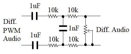 Edited 2023-04-06 10:58 by phil99 |
||||
