
|
|
Forum Index : Microcontroller and PC projects : PicoMite: driving a small speaker
| Page 1 of 14 |
|||||
| Author | Message | ||||
| thwill Guru Joined: 16/09/2019 Location: United KingdomPosts: 4308 |
Hi folks, Starting a new thread because the old one has diverged from its original topic. This thread is for discussion of filter and amplifier circuits for driving a small (e.g. 8 ohm, 0.5-1.5W) speaker from the PicoMite (specifically via PLAY SOUND if that matters). Previous threads discussing this subject, from newest to oldest: - PicoMite: can we explain/fix "ticking" when using PLAY SOUND - PicoGAME LCD: Handheld videogame (very minor discussion) - PicoMite: what the monkey made - PicoMite: driving a passive buzzer Best wishes, Tom MMBasic for Linux, Game*Mite, CMM2 Welcome Tape, Creaky old text adventures |
||||
| Volhout Guru Joined: 05/03/2018 Location: NetherlandsPosts: 5072 |
Hi Tom, The problem is not "designing a circuit". The problem is that no-one wants to accept that this may involve more electronics than an off-the-shelf-chineese circuit. I have designed many good audio circuits for this pico, but there is always demand for something else. Take my inductor filter, add a potmeter for sound volume, add the PAM83xx or LM4871 or LM386(maybe not from 5V) and you are done. If you want full SMD, take the active filter (used in Peters Latest GBP25 VGA mite), add a volume control, add PAM83xx or a LM4871, or a LM386(not 5V) and you are done. Volhout P.S. LM386 can only drive 2Vpp when powered from 5V. It may work , but may not give you the loudness you need. Edited 2023-03-24 23:24 by Volhout PicomiteVGA PETSCII ROBOTS |
||||
| thwill Guru Joined: 16/09/2019 Location: United KingdomPosts: 4308 |
Hi Volhout, "More electronics than an off-the-shelf-chinese cicruit": 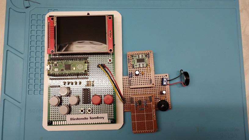 ... and not yet good enough. Now I acknowledge that I need to double-check my work, and that this isn't using your inductor filter (I did construct that on a solderless breadboard but it didn't seem any better - probably my mistake) The suggestion seems to be that the problem (if I am foolhardy enough to exclude user error) is upstream with the power-supply ... more investigation required. Thanks for all your suggestions, and the ones that will no doubt come in the future. Unfortunately I can't buy/build/test as fast as suggestions come  . .Best wishes, Tom Edited 2023-03-24 23:53 by thwill MMBasic for Linux, Game*Mite, CMM2 Welcome Tape, Creaky old text adventures |
||||
| stanleyella Guru Joined: 25/06/2022 Location: United KingdomPosts: 2548 |
https://www.ebay.co.uk/itm/134448973832?hash=item1f4dc88808:g:J-wAAOSwXfJf6tDZ&amdata=enc%3AAQAHAAAA8Ka2MqtAsnb0MXo44x1QxNJfhkkWQL7QBdniMy5f1uOxlbq10aScTZulMAHUf88pEhnHsneXCqf5U5sp9ZV%2Bc8n55FKlPgrga%2BIH9zgRBNeOgdHbMLeKJ6Ur%2Ft2WM9%2Bh4U0qPmoUOSTsp2KVgnzIwOzGl3Q1bsSyUlvzfOcRs8wdLxeuo4tMo5KyQsBQWMZJREzz9ZQpYhNqfb9pzO%2FkMn3an4IP609WsfNY95IhvzKrWfmkEmSV87OrDvNfmxJ8MDxNHjtEqBaba7Z0iFLwrLkaOyThIZEjDHOHDvc28eFjqpT2AWy7BXHXyKvAx1E0Fw%3D%3D%7Ctkp%3ABFBM_uHRxeJh |
||||
| thwill Guru Joined: 16/09/2019 Location: United KingdomPosts: 4308 |
It's lovely ... it's also 8cm x 3cm and isn't going to fit inside the Bintendo ;-) Best wishes, Tom MMBasic for Linux, Game*Mite, CMM2 Welcome Tape, Creaky old text adventures |
||||
| stanleyella Guru Joined: 25/06/2022 Location: United KingdomPosts: 2548 |
just ordered 10 pack 4.7mH chokes for £1.95 to build filter in the manual for audio. saw this circuit  |
||||
| Volhout Guru Joined: 05/03/2018 Location: NetherlandsPosts: 5072 |
@Eejit, It is very friendly of you to help us find a solution for Tom, but not every pi is the same pi. The Pi4 uses PWM output at 192kHz. If you want 20Hz...20kHz, the Pi4 has to reject 192kHz (around 10x the highest frequency 20kHz). That can be done with simple RC filter as shown in above schematics. The PicoMite runs PWM at 44kHz (2.2x the highest frequency). Using the Pi4 audio filter will not reject much of the 44kHz PWM frequency. You need a better filter. It does not harm trying, but you will end up with a lot of 44kHz (inaudible that is) and digital amplifiers (class D) will distort heavily, and cats will avoid your picomite.... Volhout PicomiteVGA PETSCII ROBOTS |
||||
| thwill Guru Joined: 16/09/2019 Location: United KingdomPosts: 4308 |
This may not be a bad thing. Despite expressing an interest in electronics I have not found mine to be an asset at the workbench. Best wishes, Tom MMBasic for Linux, Game*Mite, CMM2 Welcome Tape, Creaky old text adventures |
||||
| matherp Guru Joined: 11/12/2012 Location: United KingdomPosts: 10273 |
What about just adding an emitter follower? I seem to remember way back when this was discussed. Our signal is approximately 0.1V to 3.1V at max volume which is plenty to drive a small speaker if we can reduce the impedance. The collector could be tied to 5V to give plenty of headroom Can one of our electronics experts discuss the pros and cons |
||||
| Volhout Guru Joined: 05/03/2018 Location: NetherlandsPosts: 5072 |
@Peter, Yes, emitter follower is an option for 32 ohm headsets. But for Tom's problem (8 ohm mini speaker) that is not solution. Note that the emitter follower is essentially a class-A amplifier. Meaning that continuous power consumption is equal or greater that the amount of power you want to output. So it you want 0.5 watt maximum output power, the current consumption (even al low volume) is 0.5 watt or greater. Also requirements may differ between people looking for a solution. Some are happy with 80's game sounds, some may look into decent audio quality. Currently the PWM is running at 44.1kHz, and PWM is refreshed every 44kHz. Peripherals (PWM) are clocked at 62MHz(VGA)/66MHz(PicoMite). This gives a 10bit sound quality (10.5 bit), which is a good optimium between amplitude quality and phase quality. Simpler filters however can be made when the PWM would run at 4 x 44kHz (and still refresh the PWM at 44kHz). You would gain 2 octaves in filter rejection, but loose 2 bits in quality (10bit -> 8bit). I am not in favour of going that way, but for game sounds it would be okay. And honestly, even cats don't hear 180kHz.... Note that such a change will not make it easier to drive a loudspeaker. It would only save 4 or 6 components in the audio filter (2 or 3 per channel). At cost of sound quality. It is possible, but I prefer the current system (44kHz). Volhout P.S. the switchmode power supply: On the VGA mite, the picomite switchmode power supply automatically turns to PWM mode since the current needed to drive the monitor forces the switchmode IC to PWM mode. Not need for OPTION POWER PWM. But then still you would need a linear regulator or other solution to get rid of the ripple. Edited 2023-03-25 06:17 by Volhout PicomiteVGA PETSCII ROBOTS |
||||
| hitsware2 Guru Joined: 03/08/2019 Location: United StatesPosts: 719 |
An emitter follower must draw much more idle current in order to drive a given load . Using ( wasting ? ) more power and needing more heat sinking ..... There are a plethora of chip amps available that have minimal extra components needed . Even less than an emitter follower . my site |
||||
| Mixtel90 Guru Joined: 05/10/2019 Location: United KingdomPosts: 7889 |
An emitter follower will do something. :) A simple enitter follower has no bias so the output is either on or off. That's fine for a square wave but not for anything else. The answer is to bias it into class A. In this mode it passes sufficient current through the load to have half supply voltage at its emitter. Now the current through the load can follow a sine wave. However, the maximum voltage at the emitter cannot be higher than 2.6V (3.3v-Vbe). Note that, if you use an 8R speaker, you will have to have a current of at least 200mA in order to get 1.65V drop across it. That current will increase to 400mA at the top of the sine wave. Not good. :( To get class A to work you have to use two bias resistors on the base and AC couple the input signal. Now we also have a problem with loads. Not many of them are happy with a constant DC current, so the usual approach is to use either a resistor (cheap) or a constant current source (much nicer and more linear) then capacitor couple the output device from the emitter-load junction. This is beautifully inefficient, as is Class A. Everything runs nice and warm. Basically, an emitter follower is great as a signal line driver. I've used them to drive high impedance headphones (capacitively coupled as described above, at 300mA so the MOSFETS are on meaty heat sinks) but they are incapable of driving 8R speakers unless you have a matching transformer. Mick Zilog Inside! nascom.info for Nascom & Gemini Preliminary MMBasic docs & my PCB designs |
||||
| Volhout Guru Joined: 05/03/2018 Location: NetherlandsPosts: 5072 |
You can also use a pnp emitter follower to 5v. But still, the power consumption would extreme.... PicomiteVGA PETSCII ROBOTS |
||||
| Mixtel90 Guru Joined: 05/10/2019 Location: United KingdomPosts: 7889 |
You *can*, but please measure the voltage between base and GND *before* you connect it to a Pico. :) Mick Zilog Inside! nascom.info for Nascom & Gemini Preliminary MMBasic docs & my PCB designs |
||||
| phil99 Guru Joined: 11/02/2018 Location: AustraliaPosts: 2626 |
All the above is good as a general discussion about audio but loose sight of Tom's requirements. 1) Compact 2) Adequate quality and volume for a small handheld device. No HiFi high power output needed. This circuit from one of the threads at the top, takes the PWM clips and isolates it from the noisy Pico supply while boosting the volume. Optional filtering is done between the amplifier and the speaker. https://www.thebackshed.com/forum/ViewTopic.php?TID=15362&P=3#194596 The transistor types and speaker resistance aren't critical. Edited 2023-03-25 08:12 by phil99 |
||||
| Mixtel90 Guru Joined: 05/10/2019 Location: United KingdomPosts: 7889 |
The LM4871 is about as compact as you can get. It's mono and gain is adjustable by setting 2 resistors. It's also cheap. Only thing is, it's SMD. It will give plenty of volume from 3V, never mind 5 and is a bridged output. It's also very stingy on current. It'll drive 4R upwards. Seems to be ideal to me. Add 2 resistors, a 1uF decoupler cap and an input capacitor and you're away. I have some of these, and a few adapter boards to 8DIL, on order. I'd be happy to send him one or two to play with. :) I want to try one to see if Ican get it to drive capacitively coupled headphones switched by the jack. If so, it would be very useful. I think you can get away with a single decoupler cap for two amps (it's for the virtual ground and it's only load is the non-inverting inputs of the op-amps on the chip). Mick Zilog Inside! nascom.info for Nascom & Gemini Preliminary MMBasic docs & my PCB designs |
||||
| hitsware2 Guru Joined: 03/08/2019 Location: United StatesPosts: 719 |
If DIP is OK ......Hard to beat this one ..... my site |
||||
| thwill Guru Joined: 16/09/2019 Location: United KingdomPosts: 4308 |
Hi folks, Whilst the brain trust are thinking about the audio I thought I'd have some light relief and start figuring out the layout of the Mk2 prototype. Here it is with its older brother: 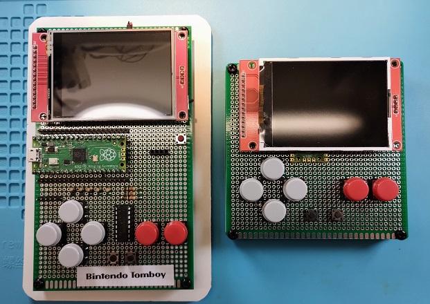 And here it is with its top off: 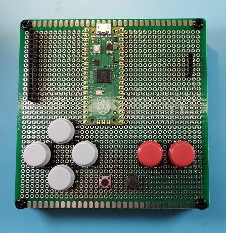 1. The area to the right of the Pico is for the audio circuitry, the speaker can go underneath. 2. The area to the left of the Pico is for the LiPo charger module. 3. The Pico is not flush mounted but sitting ontop of a set of male header pins that raise it sufficiently that the USB can still be attached, it's still just low enough that the USB cable doesn't get entangled in the SD card under the display - though I'm half inclined to desolder that and bodge a micro-SD reader in its place. 4. I haven't decided whether I'm going to include the shift-register or just wire the buttons via resistors to 8 GPIO pins. I need to decide how to allocate the GPIO and I want to keep pins for an I2C channel and a serial channel free. Best wishes, Tom Edited 2023-03-25 09:38 by thwill MMBasic for Linux, Game*Mite, CMM2 Welcome Tape, Creaky old text adventures |
||||
| lizby Guru Joined: 17/05/2016 Location: United StatesPosts: 3367 |
Stanley--if you delete everything from the "?" on, the link still works, and you don't put a long line in your post which causes the forum window to expand so that everyone in every post has to scroll to see the whole post. Better still, use the link symbol (4th icon from left below "Font"--globe with 2-link chain) and produce a clickable link to which you can provide descriptive text: Portable mini-stereo plug amplifier (3.5mm) You can click "Preview Post" to confirm that everything looks OK. PicoMite, Armmite F4, SensorKits, MMBasic Hardware, Games, etc. on fruitoftheshed |
||||
| lizby Guru Joined: 17/05/2016 Location: United StatesPosts: 3367 |
Looking good, Tom. PicoMite, Armmite F4, SensorKits, MMBasic Hardware, Games, etc. on fruitoftheshed |
||||
| Page 1 of 14 |
|||||
| The Back Shed's forum code is written, and hosted, in Australia. | © JAQ Software 2025 |
