
|
|
Forum Index : Microcontroller and PC projects : PicoMite: driving a small speaker
| Author | Message | ||||
| mozzie Regular Member Joined: 15/06/2020 Location: AustraliaPosts: 68 |
G'day Phil, Please don't take offence as I think we are on the same track here, but there are still a couple of problems to be overcome: The MONO option inverts the audio signal but the PWM carrier is still in phase, a single filter across the outputs will only work (I think) if the carrier is out of phase. There are still anomalies (breaks?) in the play sound function that come straight through the filter (either type), these are attenuated by a stereo volume control but not a mono control across the inputs. This is in the original PAM8302 circuit posted but now not recommended for this reason, and is more pronounced as the volume is reduced. These are evident on change of note etc and I don't think they can be eliminated. Testing with the original Poke Short &h40050000,&h09 showed a lot of these problems as well. My own interest in this is for sound effects generally and "steam sound" more specifically, just ideas at the moment but the minimum amount of components possible could be an advantage if thinking small scale. The buffered PWM speaker drive is perhaps still an option. And yes these are available pre-built etc but where is the fun / challenge in that? And yes, nearly 50 and back tinkering with kettles on wheels... Regards, Lyle. |
||||
| phil99 Guru Joined: 11/02/2018 Location: AustraliaPosts: 1805 |
No offence taken, I simply assumed the PWM carrier is inverted not the sound. That seemed the simplest way to do it. My testing was with PLAY TONE and POKE without an amp as my toybox has no TDA2822. |
||||
| mozzie Regular Member Joined: 15/06/2020 Location: AustraliaPosts: 68 |
G'day, Using this circuit here for sound effects etc and creates quite a bit of noise. Posting this as hopefully Tom and others may be able to use it as a basis for driving a mono speaker from the Pico. PAM8302A version is differential and Peters MONO function in play sound means almost no noise when idle.  Once again component values can be fiddled with to change filter settings and gain: R3+C4 / R5+C7 are low pass filter for PWM carrier supression, change as desired or add LC circuit. C3+VolA / C6+VolB High Pass and AC coupling (C3 / C6 optional but recommended) C5+R4 / C8+R6 are High Pass and AC coupling to PAM Chip R4 / R6 set PAM8302A gain as per data sheet, RTFM Keep the AudioA / AudioB paths the same, differences will cause balance (noise) problems. 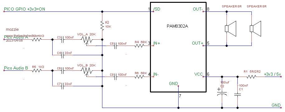 Will also work with Play tone and Poke &h40050000,&h09 for same frequency both channels or use different frequencies for odd effects, gain will need to be lowered. PAM8302A Datasheet from Element14 is recommended, others are missing an important f in gain calculation. Have a good (long) weekend.  Lyle. |
||||
| thwill Guru Joined: 16/09/2019 Location: United KingdomPosts: 3852 |
Thanks Lyle, I look forward to trying it out when the bits arrive. Enjoy your Easter weekend, Tom Game*Mite, CMM2 Welcome Tape, Creaky old text adventures |
||||
| Turbo46 Guru Joined: 24/12/2017 Location: AustraliaPosts: 1595 |
@Mossie, Is it possible to reduce the component count of that circuit? - Remove C3 and C6 because you are AC coupling the output of the pot, I don't think it is also necessary to AC couple the input as well. - Remove R4 and R6. I presume that they are there to attenuate the signal to the PAM. Why not increase the value of the 1k3 filter resistors to attenuate the signal at that point? With appropriate changes to the filter capacitors of course. Bill Keep safe. Live long and prosper. |
||||
| Mixtel90 Guru Joined: 05/10/2019 Location: United KingdomPosts: 5749 |
R4 and R6 set the gain, it's not simple attenuation. They are necessary even though they don't look it. :) Mick Zilog Inside! nascom.info for Nascom & Gemini Preliminary MMBasic docs & my PCB designs |
||||
| Turbo46 Guru Joined: 24/12/2017 Location: AustraliaPosts: 1595 |
Thanks Mick, that will teach me to go off half cocked (maybe). I still have not looked at the data sheet but as I do understand how differential amplifiers work that sounds right. I would have expected the gain to be set after the differential input stage though. Bill Keep safe. Live long and prosper. |
||||
| Mixtel90 Guru Joined: 05/10/2019 Location: United KingdomPosts: 5749 |
It caught me out too, when I was looking at the LM4871. :) Mick Zilog Inside! nascom.info for Nascom & Gemini Preliminary MMBasic docs & my PCB designs |
||||
| thwill Guru Joined: 16/09/2019 Location: United KingdomPosts: 3852 |
Hi folks, Finally found time to build @mozzie's last posted circuit (but with only one speaker) and this, plus Peter's improvements to the firmware (especially the Mono flag to PLAY SOUND), plus a marginally better speaker, plus switching to triangular waveform, plus switching up an octave have produced a satisfactory result - Thank you!!! 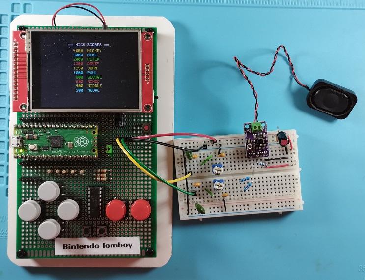 It draws ~110 mA when running, which on a 2500 mAh battery gives much more battery life than it needs. The only problem I had was with the little potentiometer on the PAM8302A, none of my screwdrivers would bite (and I suspect it should be a plastic "screwdriver" anyway) and I ended up using needle nose pliers which wasn't great. Can anyone tell me what tool I'm supposed to use ? 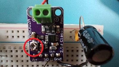 Best wishes, Tom Game*Mite, CMM2 Welcome Tape, Creaky old text adventures |
||||
| Mixtel90 Guru Joined: 05/10/2019 Location: United KingdomPosts: 5749 |
I can't remember what I used now. Probably one of those little screwdrivers used for tightening the screws in glasses. Mick Zilog Inside! nascom.info for Nascom & Gemini Preliminary MMBasic docs & my PCB designs |
||||
| thwill Guru Joined: 16/09/2019 Location: United KingdomPosts: 3852 |
They would be too small. I have very small screwdrivers ... and glasses. Best wishes, Tom Game*Mite, CMM2 Welcome Tape, Creaky old text adventures |
||||
| matherp Guru Joined: 11/12/2012 Location: United KingdomPosts: 8600 |
If you have a surplus of those white pointers that come with displays then just sand one down to make a suitable screwdriver 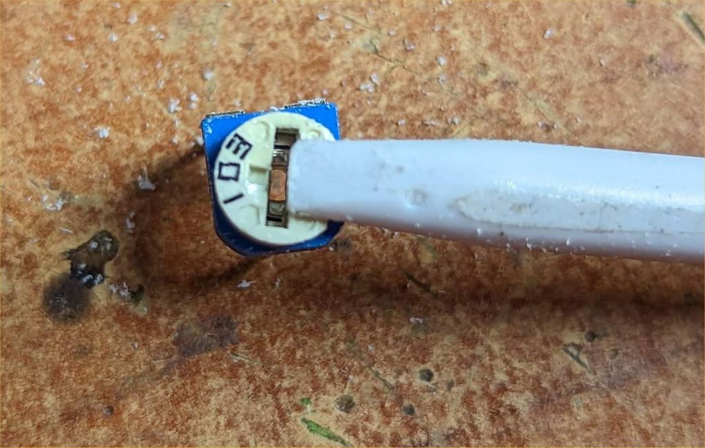 |
||||
| Mixtel90 Guru Joined: 05/10/2019 Location: United KingdomPosts: 5749 |
I have various little screwdrivers - that's why I can't remember what I used on that sort of pot. :) I also have special trimming tools. I don't think I have any of those pots at present so I can't try one. Mick Zilog Inside! nascom.info for Nascom & Gemini Preliminary MMBasic docs & my PCB designs |
||||
| thwill Guru Joined: 16/09/2019 Location: United KingdomPosts: 3852 |
Thanks guys, after some digging I found a 6 pronged non-pointy thing in my cheap phone "repair" kit, which after I overcame my distaste for poking something metal into the pot seemed to do the job ... even though it obviously expects a 4 prong thing ¯\_(ツ)_/¯. I may still shave down a screen stylus though, I have at least 3 knocking about. Best wishes, Tom Edited 2023-05-08 02:24 by thwill Game*Mite, CMM2 Welcome Tape, Creaky old text adventures |
||||
| thwill Guru Joined: 16/09/2019 Location: United KingdomPosts: 3852 |
Peter, regarding your photo. Why have you mounted a potentiometer onto the top of a Crème Brulé? Can we run MMBasic on cold desserts now ?  Best wishes, Tom Edited 2023-05-08 03:57 by thwill Game*Mite, CMM2 Welcome Tape, Creaky old text adventures |
||||
| Turbo46 Guru Joined: 24/12/2017 Location: AustraliaPosts: 1595 |
Isn't that a small philips head screwdriver AKA cross head? Any self respecting jewellers screw driver set should have one to suit. I'm surprised that your phone repair kit doesn't. Knitting needles and crochet hooks can be filed down too. RF tuning tools are handy too. Bill Keep safe. Live long and prosper. |
||||
| thwill Guru Joined: 16/09/2019 Location: United KingdomPosts: 3852 |
That's what it looks like, but it's shallow and the "cut" is not terribly well defined. I have a large selection of small Philips screwdrivers and couldn't get one to bite ... perhaps I was just being more than usually incompetent, let's not worry about it. Best wishes, Tom Game*Mite, CMM2 Welcome Tape, Creaky old text adventures |
||||
TassyJim Guru Joined: 07/08/2011 Location: AustraliaPosts: 5915 |
To use a Philips head driver, you probably have to grind the tip off. I prefer plastic flat blades but sometimes it needs metal get get it moving. Jim VK7JH MMedit MMBasic Help |
||||
| Volhout Guru Joined: 05/03/2018 Location: NetherlandsPosts: 3562 |
Maybe a bit late in the game,but what about this .... small speaker + amplifier PicomiteVGA PETSCII ROBOTS |
||||
| thwill Guru Joined: 16/09/2019 Location: United KingdomPosts: 3852 |
Very pretty, but having tested it satisfactorily and now soldered it to the Mk 2 prototype I think I'm basically* satisfied with what @mozzie proposed. * On @Turbo46's suggestion I've removed/shorted C3 and C6 and replaced the stereo pot with a single 50K pot (as a variable resistor) between IN+ and IN-, this seems to be how the tiny 10K pot (set to 0 for my build) on the module works - tell me I'm wrong. Can someone explain what is going on with /SD. It's "shut down" and the bar means it is active low (?), and the module contains a 10K pull-up to VCC so if left disconnected it won't do anything will it ? @mozzie's schematic adds a 10K pull-down so if there is no signal from the Pico GPIO line then ... ? Best wishes, Tom Game*Mite, CMM2 Welcome Tape, Creaky old text adventures |
||||
