
|
|
Forum Index : Microcontroller and PC projects : PicoMite: driving a small speaker
| Author | Message | ||||
| Turbo46 Guru Joined: 24/12/2017 Location: AustraliaPosts: 1638 |
Thank you for trying to inject some sanity into this post. Going back to Phil's post that he linked to, he also says :'The output filter makes no audible difference, though the scope shows it greatly reduces the 44kHz at the speaker.' The output filter makes no audible difference This suggest to me that the speaker and our ears are pretty good at filtering out the PWM frequency. If some of it gets through to the speaker then it is of no consequence. If your cat runs to the other end of the house and bats fall from the sky then you may have to address it, until then... Since the signal is being fed through an audio amplifier a filter is necessary to recover the audio signal from the PWM. I would stick with a single one stage RC filter for the time being at least until the circuit is performing satisfactorily. Two stages would be better but less compact - a single stage LC filter would give the same result and be just as compact. From what I've seen on the web, the amplifier seems adequate for the job so I would stick with that. Bill Keep safe. Live long and prosper. |
||||
| mozzie Senior Member Joined: 15/06/2020 Location: AustraliaPosts: 132 |
If the original question is the simplest / low cost / minimal approach to driving a small low cost / quality speaker from a Pico then a simple push / pull emitter follower with output cap works fine here 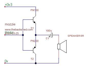 Yes its LO-FI Yes there is a little hiss Yes it may be outputting 44khz (but I cant hear it) Yes the output is only about 2v p-p @ 40khz and the audio is below that But it is simple  Regards, Lyle. P.S. Just found Phil99's original post and that is an elegant solution: https://www.thebackshed.com/forum/ViewTopic.php?TID=15362&P=3#194596#194596 with only a couple of extra components. Edited 2023-03-25 12:39 by mozzie |
||||
| Turbo46 Guru Joined: 24/12/2017 Location: AustraliaPosts: 1638 |
Hiss That appears to be the main problem at the moment. I suspect that it is coming from the Pico (all of those little switches inside going 19 to the dozen). From memory, Tom has taken no great effort to beef up the power supply circuitry on the bread board and that is where a well designed PCB would help as would some more bypass capacitors. I would like to suggest some tests to find out for sure where it is coming from: 1. Disconnect the amplifier input at the input to the volume control pot. Is the hiss still there? If so, the noise on the power supply is probably affecting the amplifier. I would try a decoupling circuit, say a 10R resistor followed by a 100u electro and an 0.1u capacitor. Only if necessary. Hopefully that should help. 2. Is the hiss coming from the supply (as I suspect)?. With the amplifier still disconnected as above put two back to back diodes across the input to the volume control pot, just to protect the amplifier from any spikes. You can remove them later. Connect the volume control input to the positive supply via a small capacitor (0.047uF or there about). If you hear the hiss now then the supply is the culprit and surely would be getting to the PWM signal. If that is so then I would try the circuit previously suggested by mozzie. Feed it from your positive supply (no 5v available) omit the 4K7 (R3), 1K will be OK for R2, 10uF will probably do for C1. Connect the output (the transistor collector) to what ever filter you are using now and from there to the volume control pot. Don't worry about any rise and fall times of the transistor, you don't need HiFi, it is of no consequence The theory behind that is that if there is noise (hiss) on the power supply then it will get through to the PWM signal and eventually to the speaker. Using the decoupled supply and the extra transistor should remove that noise and give you a clean PWM signal. Hope that helps. Bill Keep safe. Live long and prosper. |
||||
| Turbo46 Guru Joined: 24/12/2017 Location: AustraliaPosts: 1638 |
If mozzie's circuit above is acceptable then an H-Bridge will give a higher output if you need it. Like Phil's circuit - let the ears and the speaker do the filtering. Bill Keep safe. Live long and prosper. |
||||
| phil99 Guru Joined: 11/02/2018 Location: AustraliaPosts: 2593 |
Some experimenting today. Feeding the raw PWM signal straight in to an LM386 linear audio amp, no filter on either input or output, resulted in what I think is perfectly acceptable sound. Rather than come up with more stuff for you to buy, this should work with whatever amp you already have. If you have one with a bridge output you will get more volume, useful with a 3.6V battery supply. Even a class D chip should work as it's PWM frequency will be in the hundreds of kHz. It should see the 44kHz as just another audio signal, unless it has it's own low pass filter on the input. If you happen to have an LM386 the connections I used are:- pin 2 - 1k to Gnd pin 3 - 1k to PWM signal pin 4 - Gnd pin 5 - 100uF to speaker pin 6 - V+ (5V or battery) Volume control is a 100R pot in series with the speaker. Pins 1,7,8 - NC Edited 2023-03-25 17:07 by phil99 |
||||
| Turbo46 Guru Joined: 24/12/2017 Location: AustraliaPosts: 1638 |
Requirements: 1) Compact. 2) Adequate quality and volume for a small handheld device. 3) No HiFi high power output needed. 4) Must work with 3.3v supply. LM386 Features • Battery Operation • Minimum External Parts • Wide Supply Voltage Range: 4 V–12 V or 5 V–18 V Will it work reliably on 3.3v and lower as the battery runs down a bit? Bill Keep safe. Live long and prosper. |
||||
| phil99 Guru Joined: 11/02/2018 Location: AustraliaPosts: 2593 |
"Will it work reliably on 3.3v and lower as the battery runs down a bit?" The one I have does. It's blaring at me now at 2.1V (ok blaring is an exaggeration but it is still loud enough). As the PWM is driving it into clipping anyway it does not need to have "headroom" voltage for linear operation. After a bit more testing there is a rise in distortion as the voltage goes below 3.3V so the LM386 is not the best choice for battery operation. It does however demonstrate that a linear amp will boost a PWM signal with acceptable results. Tom, try the ones you have and see what happens. Edited 2023-03-25 21:30 by phil99 |
||||
| matherp Guru Joined: 11/12/2012 Location: United KingdomPosts: 10209 |
Here is a circuit tested in the silicon - none of this LT spice nonsense. Measurement is across an 8ohm load 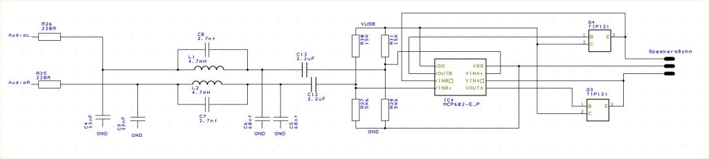 No clipping. Nice sinewave Tested from 30Hz to 10000Hz 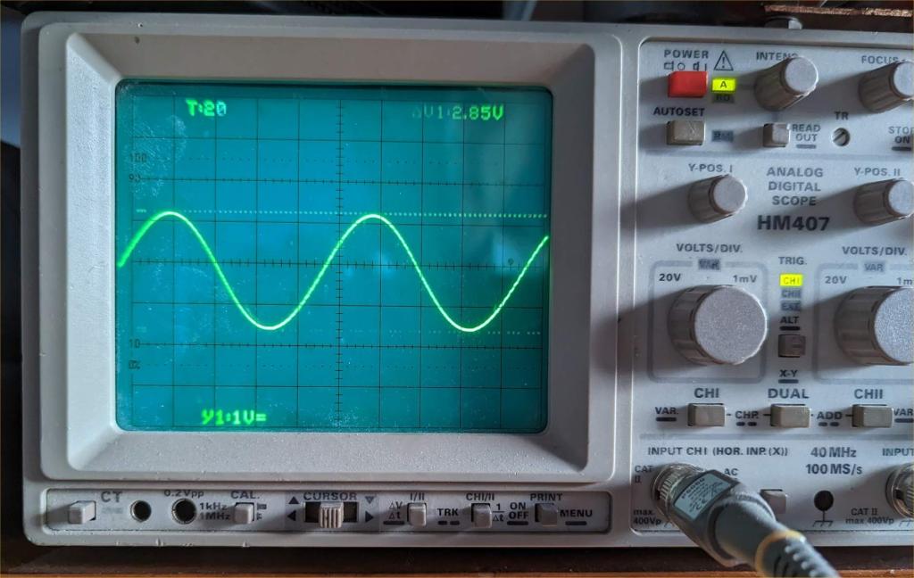 Edited 2023-03-25 23:22 by matherp |
||||
| Mixtel90 Guru Joined: 05/10/2019 Location: United KingdomPosts: 7833 |
Nice, classic op-amp output driver circuit. :) Do you find that the transistors warm up nicely, particularly on low frequency sine waves? Mick Zilog Inside! nascom.info for Nascom & Gemini Preliminary MMBasic docs & my PCB designs |
||||
| thwill Guru Joined: 16/09/2019 Location: United KingdomPosts: 4301 |
LOL, ordered half a dozen of them this morning  . . That will be easy, I don't have any op amps, just some microcontrollers, passives, digital logic ICs and AliExpress modules. For full disclosure @Volhout has offered to provide a full circuit and since my own efforts are, even with all the support, not working out I have accepted his offer. I'll still be poking and reporting on my own findings, but only in the hopes of learning something by osmosis. Best wishes, Tom Edited 2023-03-25 23:42 by thwill MMBasic for Linux, Game*Mite, CMM2 Welcome Tape, Creaky old text adventures |
||||
| Mixtel90 Guru Joined: 05/10/2019 Location: United KingdomPosts: 7833 |
FYI, Tom, you can bias a CMOS inverter into linear mode using a resistor from output to input. In fact, you can even make a small amplifier capable of driving a tiny speaker or earpiece from one. However they don't have much output current availability so you usually have to parallel several up to get them to be useful. :) Mick Zilog Inside! nascom.info for Nascom & Gemini Preliminary MMBasic docs & my PCB designs |
||||
| matherp Guru Joined: 11/12/2012 Location: United KingdomPosts: 10209 |
I'm not very knowledgeable on analogue electronics. However, the one thing I do know is that audio amplifier modules are likely to be unsuitable. We need amplification of current not voltage. Most audio amplifiers have voltage gains of 20 or even greater whereas we need a gain of not more than 5V/3.3V to avoid clipping and a horrible sound. |
||||
| stanleyella Guru Joined: 25/06/2022 Location: United KingdomPosts: 2529 |
many amps are bridged like car amps so 4 times the power for same supply. |
||||
| mozzie Senior Member Joined: 15/06/2020 Location: AustraliaPosts: 132 |
G'day Peter, That scope shot certainly proves the filter circuit is doing a great job, I think I might need to order some 4.7mH inductors... As you suggest, we need current gain rather than voltage gain, the emitter follower provides exactly that. Did you measure the output into a speaker or a resistor? the 1.4v offset in the output is probably not going to go well with a speaker voice coil, they normally don't like anything more than a few mV, hence the reason for coupling capacitors in single supply amps (unless BTL) A little off topic, are you planning to include the "p" and "n" (white noise) options for the play sound function in the next release of PicoMite MMbasic? they are handy for things like steam sound generators |
||||
| Mixtel90 Guru Joined: 05/10/2019 Location: United KingdomPosts: 7833 |
Peter's circuit has the same problem that simple ones tend to do - they put the output current through the speaker. What that does is pull (or push) the cone away from its centre position so that it will start to bang against the pole piece (or come out of the pole piece) on peaks in the music. Those peaks will be a lot lower than its normal power handling rating. It's never a good idea to have this sort of thing happening. The answer is to use a power resistor as the load and then couple the speaker across it via a capacitor. Unfortunately that also brings problems. Half the power is lost in the resistor (so it runs hot) and there is less available for the speaker. Also, the value of the capacitor restricts the lowest frequencies that can be delivered. Some headphones simply won't handle any amount of DC through their coils and distort horribly if there is more than a mA or two. That's because the diaphragm moves such a short distance anyway. mozzie's PNP/NPN circuit may be a better bet. Something similar, with a biasing arrangement anyway. It might be better to run it from 5V and use a third transistor (common emitter) to drive the output pair. It does start to get a bit bulky though, as do heatsinks for class A. :) Mick Zilog Inside! nascom.info for Nascom & Gemini Preliminary MMBasic docs & my PCB designs |
||||
| Volhout Guru Joined: 05/03/2018 Location: NetherlandsPosts: 5036 |
@peter, Nice analog scope…. Volhout PicomiteVGA PETSCII ROBOTS |
||||
| matherp Guru Joined: 11/12/2012 Location: United KingdomPosts: 10209 |
Circuit works nicely with 8ohm across the speaker/1000uF cap - still lovely clean sine wave and music plays as expected and all DC gone Sample recorded on phone from speaker My recording 4.zip Edited 2023-03-26 02:40 by matherp |
||||
| matherp Guru Joined: 11/12/2012 Location: United KingdomPosts: 10209 |
Thanks. Hameg HM407 Analog with digital storage as well Yes Now fixed as per Mixtel's change so no more DC offset and waveform across speaker just as good (1000Hz) Note change of bias resistors - now 12K to GND and 15K to 5V Check out the recording in the post above 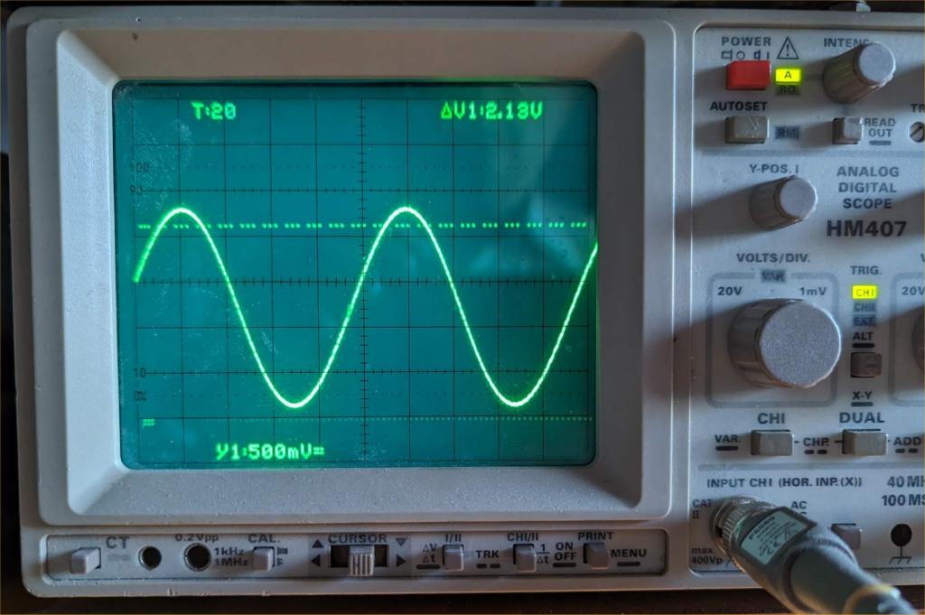 Edited 2023-03-26 02:53 by matherp |
||||
| mozzie Senior Member Joined: 15/06/2020 Location: AustraliaPosts: 132 |
Sounds good Peter Considering the audio output from the Pico is virtually identical to a Class "D" amplifier (at lower frequency) I still think for direct drive of a speaker we are better off simply buffering it for more current drive and applying a little filtering before the speaker, this means no biasing and the transistors are always on or off so no heat generation. This is ok for the LO-FI side anyway. 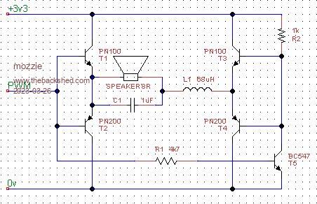 This is the bridge version of the one above, although its starting to get more complicated than an integrated amp  It does a very good job with steam sound effects and tones, I'll have to sort out some music to try to see how it does. Sadly all these years of tinkering with audio hasn't made me a very good programmer..  Regards, Lyle |
||||
| Mixtel90 Guru Joined: 05/10/2019 Location: United KingdomPosts: 7833 |
But the inductor alone is almost the size of the LM4871... And I ordered 10off LM4871 for 3.04 UKP including postage. Don't you just hate silicon sometimes? Mick Zilog Inside! nascom.info for Nascom & Gemini Preliminary MMBasic docs & my PCB designs |
||||
| The Back Shed's forum code is written, and hosted, in Australia. | © JAQ Software 2025 |
