
|
|
Forum Index : Microcontroller and PC projects : PicoMite: driving a small speaker
| Author | Message | ||||
| Mixtel90 Guru Joined: 05/10/2019 Location: United KingdomPosts: 5760 |
Yes, Tom, they are valves - and yes, I was joking too. :) Nope - it's GIGO I'm afraid. Good speakers will show up a poor sound source. Weak speakers won't sound too bad if the source is decent. That's why modern music systems can sound quite reasonable even though the drivers are only 2" in diameter and are in plastic boxes. The idea of the speakers being the important link in the chain is an old idea now. Mick Zilog Inside! nascom.info for Nascom & Gemini Preliminary MMBasic docs & my PCB designs |
||||
| Turbo46 Guru Joined: 24/12/2017 Location: AustraliaPosts: 1595 |
That's debatable but speakers don't generate noise. Bill Keep safe. Live long and prosper. |
||||
| lizby Guru Joined: 17/05/2016 Location: United StatesPosts: 3027 |
If you discount the quality of the ears of the listener. With 76-year-old ears, it doesn't very much matter how good the speakers are. PicoMite, Armmite F4, SensorKits, MMBasic Hardware, Games, etc. on fruitoftheshed |
||||
| stanleyella Guru Joined: 25/06/2022 Location: United KingdomPosts: 1654 |
as long as it's got bass :) |
||||
| Turbo46 Guru Joined: 24/12/2017 Location: AustraliaPosts: 1595 |
@mozzie, Did you try the bridge circuit without the filter please? Bill Keep safe. Live long and prosper. |
||||
| phil99 Guru Joined: 11/02/2018 Location: AustraliaPosts: 1811 |
Hi Tom, As you have LM386 chips on the way you may as well try one on a breadboard. Run it from your battery and decide for yourself if the quality is satisfactory. Edit. Retested at 2.9V. PLAY WAVE distortion vanishes when PLAY VOLUME is below 90%. PLAY SOUND is free of distortion with all 4 tones at Volume 24 Meanwhile here is a revised version of the transistor circuit. Two components added to improve performance below 3V. No values are critical. Capacitor values are suggested minimum. The 1N5819 could be any Schottky diode. Used BC547 just because you have them. 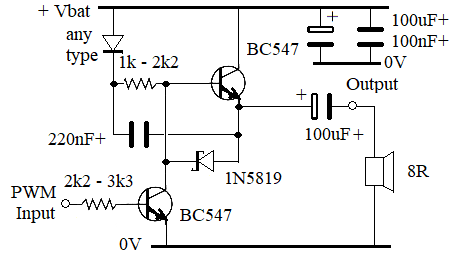 Edited 2023-03-26 12:41 by phil99 |
||||
| mozzie Regular Member Joined: 15/06/2020 Location: AustraliaPosts: 68 |
@Bill 220R protection resistors are a great idea, will fit just in case  I have tried the circuit with and without filter and the only difference is slightly increased audible hiss without (on 3v3) and higher current draw: current Filter No-filter 3V3 55mA 68mA 5V1 80mA 100mA @Tom Toms_Tunes.zip Above recording is with filter as shown on bridged emitter follower circuit, without filter sounds no different to me but the microphone pics up the carrier and causes problems with recording, so its definitely there  PLEASE NOTE: Recording made through my SPL meter microphone as its all I have that'll work with a sound card on this PC, and I know it has filters in it but the output sounds pretty close on playback. Another issue I think is with Play Sound itself, modulation is 25% with 1 sound, 50% with 2 sounds etc. so you only get full output with 4 sounds running. Play Tone and Play WAV are 100% modulation and generate far more output (quite loud) this is what my scope tells me anyway. Regards, Lyle. P.S. I'm running 5.07.07b28 and the speaker is a 35mm / 5w / 8R in a plastic enclosure, probably not much response below 200Hz Edited 2023-03-26 13:45 by mozzie |
||||
| Turbo46 Guru Joined: 24/12/2017 Location: AustraliaPosts: 1595 |
Thanks mozzie, That sounds good to my old ears. Much better than the buzzer verion. I wonder whether an H-bridge chip could do the same? More compact. I'd be interested in what Tom thinks. The extra current draw may be an issue for him though but depending how loud it is a series resistor might tame it a bit. Bill Keep safe. Live long and prosper. |
||||
| thwill Guru Joined: 16/09/2019 Location: United KingdomPosts: 3859 |
Hi folks, Thanks for the continued responses and many thanks to Bill for trying to wrangle for me. I've got a few quality hours today so I'm hoping I might make some progress in my own investigation - I think my board has a source of noise pre-amp/filter that I need to track down. Thanks @mozzie, If I can get something close to that I would be very happy indeed, though my (current) speaker is just a 22mm / 1.5W / 8R device. Would it be possible for you to post a complete schematic from Pico PWM output to speaker - or point me at exactly which one of the past posts is under discussion. Thanks @phil99, I'll look at putting your circuit together on a breadboard today. And thanks to everyone else too. Best wishes, Tom P.S. I *think* the code I posted a link to: https://github.com/thwill1000/mmbasic-lazer-cycle/blob/main/src/spmusic.bas should also play Vivaldi's "Spring" if you uncomment lines 54-55. Edited 2023-03-26 18:04 by thwill Game*Mite, CMM2 Welcome Tape, Creaky old text adventures |
||||
| mozzie Regular Member Joined: 15/06/2020 Location: AustraliaPosts: 68 |
G'day Tom, as requested, full circuit diagram for Emitter-Follower Bridge Amp. 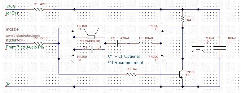 Have a play and see how it goes, as others have suggested, there are numerous ways to go with audio amplification. Only issues known are fairly high current (not as bad as some / worse than others) and no voltage gain / volume control so your speaker sensitivity will determine the volume level. As indicated, L1 and C1 are optional filter, not mandatory and I think 68uH might be overkill, C3 recommended as without PWM the current is minimal. @Turbo46 A H-Bridge chip should work and a couple look interesting so might require further investigation. Be nice if we could get some in DIP8 package  @Phil99 That is a neat amplifier circuit and the addition of the bootstrap cap for low supply operation is interesting... Another breadboard full of bits  Regards, Lyle. Edited 2023-03-26 23:16 by mozzie |
||||
| lizby Guru Joined: 17/05/2016 Location: United StatesPosts: 3027 |
Thank you. That reminded me that I had had a problem before with the PAM8403: PAM8403 issue with F4 Also this thread for more PAM8403 issues/solutions: PAM8403 Maybe over-voltage was the problem there. Can you suggest the appropriate values for the resistors for fitting with a PicoMite? ~ Edited 2023-03-27 00:22 by lizby PicoMite, Armmite F4, SensorKits, MMBasic Hardware, Games, etc. on fruitoftheshed |
||||
| Mixtel90 Guru Joined: 05/10/2019 Location: United KingdomPosts: 5760 |
I'd guess that, as the PicoMite will put out around 3V max then a 2:1 ratio should be ok to get around 1V max output. Maybe 1k and 470R. If it's still too loud then either increase the 1k or reduce the 470R. The PAM has too much gain and it's input is a bit fragile. The ideal is to use an amp with a lot less gain. I expect that the PAM modules are set for maximum (24dB) gain, where the input resistor is 18k. That can be increased up to 142k according to the data sheet, so it might be interesting to attempt adding as series resistor of 120k first. The second stage of the amp has a gain of 2, so this *might* get the gain down to around 3-ish. Mick Zilog Inside! nascom.info for Nascom & Gemini Preliminary MMBasic docs & my PCB designs |
||||
| Volhout Guru Joined: 05/03/2018 Location: NetherlandsPosts: 3573 |
Hi Mozzie, For arduino 3d printers there are small cheap modules with DRV8838 or 8837. These half bridge divers mounted on a breadboard friendly pcb are nice high power output stages for your pwm solution. Btw, a 100uH inductor gives a friendlier response than the 68uH. Volhout PicomiteVGA PETSCII ROBOTS |
||||
| thwill Guru Joined: 16/09/2019 Location: United KingdomPosts: 3859 |
Hi folks, I'm still messing about with the PAM as I've already got it wired up and it sort-of works and IMO is good enough for experimental poking. If I'm only using one of the pair of PWM outputs (because I'm only driving a mono filter => amp => speaker) then what should I do with the other PicoMite PWM pin, should it be flapping in the wind, tied to ground through an ### ohm resistor, or something else ? Best wishes, Tom Game*Mite, CMM2 Welcome Tape, Creaky old text adventures |
||||
| Volhout Guru Joined: 05/03/2018 Location: NetherlandsPosts: 3573 |
Hi Tom, If your sound is mono in character (you program it, so you should know) you can leave the pin unconnected. In case of "stereo sound" that should sound via a mono speaker, you could connect both PWM outputs via identical resistor values to the first capacitor in the filter. Volhout PicomiteVGA PETSCII ROBOTS |
||||
| thwill Guru Joined: 16/09/2019 Location: United KingdomPosts: 3859 |
Thanks @Volhout, this fix made. Tom Game*Mite, CMM2 Welcome Tape, Creaky old text adventures |
||||
| Turbo46 Guru Joined: 24/12/2017 Location: AustraliaPosts: 1595 |
If no signal that you want is on that pin then I would leave it 'flapping in the wind'. Connecting it into your output circuit has the potential to just add more noise. Bill Keep safe. Live long and prosper. |
||||
| mozzie Regular Member Joined: 15/06/2020 Location: AustraliaPosts: 68 |
G'day all, after a bit more tinkering, this might be as simple as its possible to get and still output around 2v across an 8R load from 3v with as few components as possible. 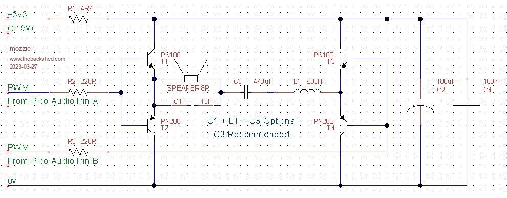 You will need to invert the second PWM output: POKE SHORT &h40050000,&h09 Hopefully this won't stuff anything else up  This gives about 25% more output than the more complicated version, will only work with mono signal sent to both outputs. Also allows shutdown: POKE SHORT &h40050000,&h01 Signals now in phase so no output. POKE SHORT &h40050000,&h09 Signals 180 out of phase so audio output. @Volhout Those modules are very interesting, a few are heading here in the post  Removing non-hand-solderable packages from the suppliers search criteria severely limits what is available, I hadn't even looked at these. Time for bed.... Regards, Lyle. |
||||
| thwill Guru Joined: 16/09/2019 Location: United KingdomPosts: 3859 |
Hi folks, I know you've pretty much dismissed the PAM8403, but (a) I'm like a dog with a bone, and (b) I'm working at my own pace and at least two pages back in this thread. I'd appreciate comments on whether I have made the correct changes to the schematic that have been suggested or whether my placement of resistors and capacitors is the result of a fever dream. 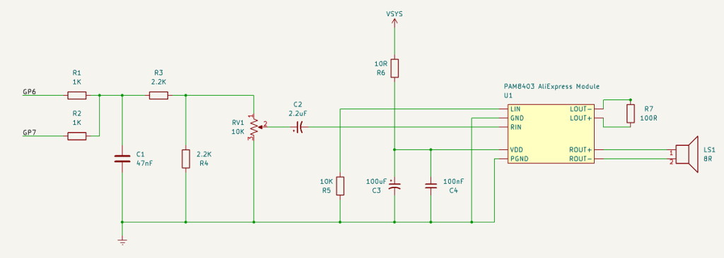 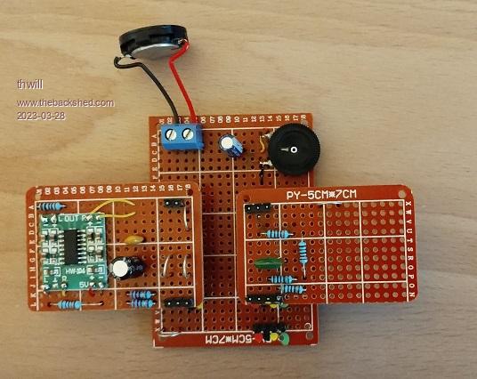 Also is this the correct capacitor arrangement that has been suggested on the power supply to my project: 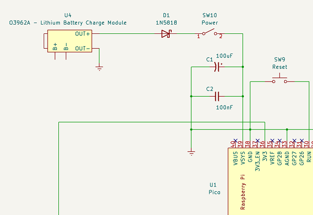 All of this presupposes that the schematic and actual device match  . .Thanks in advance, Tom Edited 2023-03-28 04:49 by thwill Game*Mite, CMM2 Welcome Tape, Creaky old text adventures |
||||
| Mixtel90 Guru Joined: 05/10/2019 Location: United KingdomPosts: 5760 |
Looks ok, I think. If you find that the volume control is a bit touchy then try adding a resistor in series with C2. That should reduce the gain of the amp, I think. Try anything up to 120k - the higher the value the less gain you should get. The power supply looks ok. If you only want one USB socket exposed you can get a 5V supply to the charger module from VBUS. Just connect it to In+ on the charger. Note that battery -ve does not go to GND, it has to go to B- on the charger. Mick Zilog Inside! nascom.info for Nascom & Gemini Preliminary MMBasic docs & my PCB designs |
||||
