
|
|
Forum Index : Electronics : Bryan's Inverter build
| Author | Message | ||||
disco4now Guru Joined: 18/12/2014 Location: AustraliaPosts: 1000 |
Hi Bryan, I am interested in the answer to this as I have one of these toriods , but my understanding is you would need to add extra turns to get both windings up to the same number of turns. i.e need to add 18 turns to the 197 (230V) to get it to match the 215 on the 250V winding. Gerry Latest F4 Latest H7 FotS |
||||
Bryan1 Guru Joined: 22/02/2006 Location: AustraliaPosts: 1450 |
Finally got around to making the Anderson connection and with only 25sqmm in a 175 amp lug it is a loose fit so plenty of solder needs to go in. I used one of my stands to hold the wire nice and upright and got a good solder joint done.  Then onto the positive cable and on stripping the end I went WTF  water damaged cable that in noway will suck up any solder. water damaged cable that in noway will suck up any solder.So back to the 12 volt shop where they made me a new cable with a 6mm hole in the lug and gave me a pair of 25sqmm x 6mm lugs for free. So in the morning the negative lead will get a 6mm lug cause as far as a M5 bolt securing a lug with a 10mm hole doesn't appeal to lasting.I do have my old Fluke 865 scope meter so I will use that for setting the voltage and looking at the waveform to make sure it's running properly. Cheers Bryan |
||||
| Bryan1 Guru Joined: 22/02/2006 Location: AustraliaPosts: 1450 |
I was looking at that old hercus cnc lathe I have here which I'm stripping and when I saw the mains transformer it was like WOW look at the size of it. 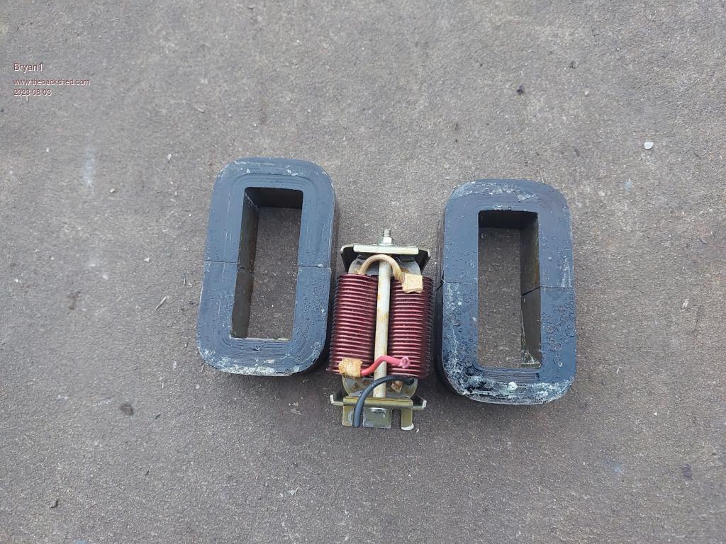 Shown in the centre is the smaller inductor off the aerosharp so from the size of them should be able to get some thick wire going thru for my next inductors. Cheers Bryan |
||||
| Murphy's friend Guru Joined: 04/10/2019 Location: AustraliaPosts: 671 |
If those cores are from a "mains" (50Hz) transformer then the laminated core might not be suitable for an inverter choke unless its a warpinverter. There is more to cores than the hole size Bryan. |
||||
| Bryan1 Guru Joined: 22/02/2006 Location: AustraliaPosts: 1450 |
G'Day Guy's, Well it has been awhile and that ol Kipoint inverter just keeps chugging along nicely with the loads I put on. I scored a bar fridge and used that as a dumpload and remembered I did have that BP charge controller that powered the array when we bought the farm back in '03. So I found it and connected it up and sure enough it worked So that forklift battery 24 volt 735AH I've been using for the last 12 years has come back to life where the SG is is sitting on 1025 and that old reg is working nicely. Now it's a 22 amp regulator and I did see one morning after leaving the fridge on all week it went back into charge mode and when I touched it man it was hot. With that solar I scored for free that regulator is working flat out at 22 amps which is the stated current max on the reg. Got all the bits I need to finish this ching inverter board so this weekend is planned to get it finished and my 180 amp mig is going to be the test as I did start to make a mig/tig trolley then the kipoint refused to power the mig so it sits unfinished. I did buy most of the bits for the Mad board inverter and just need to grab some of the small caps to finish the component list. Now as far as just soldering thick wire direct to a pcb got me thinking so I have bent up some of those M4 pcb connectors and they fit to a tee on the PCB. So my plan is put them on the PCB and use some copper plate soldered to the cable then drilled to suit the M4 connectors. Then if needed they can be taken off where a solid soldered wire won't allow that to happen. Anyway over the weekend pic's will happen as this ching build goes ahead and hopefully it will work. Cheers Bryan |
||||
| Bryan1 Guru Joined: 22/02/2006 Location: AustraliaPosts: 1450 |
G'day Guy's, Well the Ching inverter project is 99.9% finished with just the ground wires to finish so here's some pic's as promised. 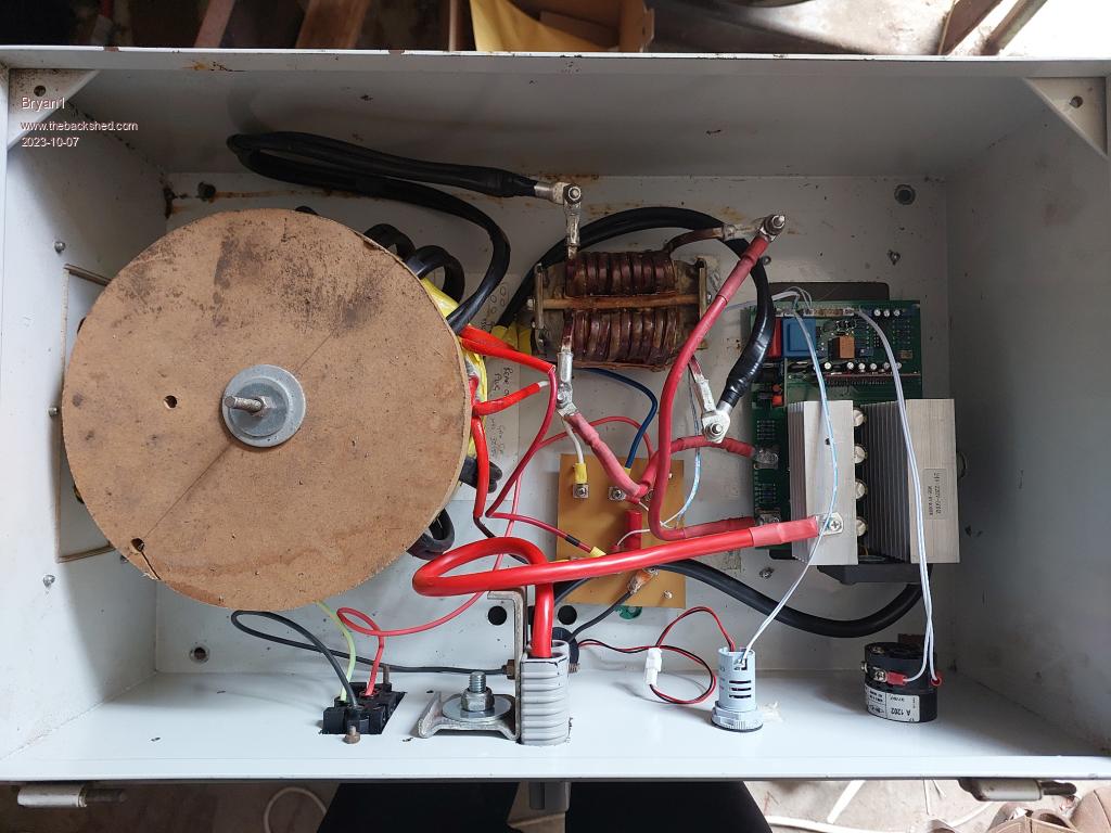 Here's a pic of the side of the box now I just used the original off/on switch that was on the box and that square object is a ali express AC volt and current meter. 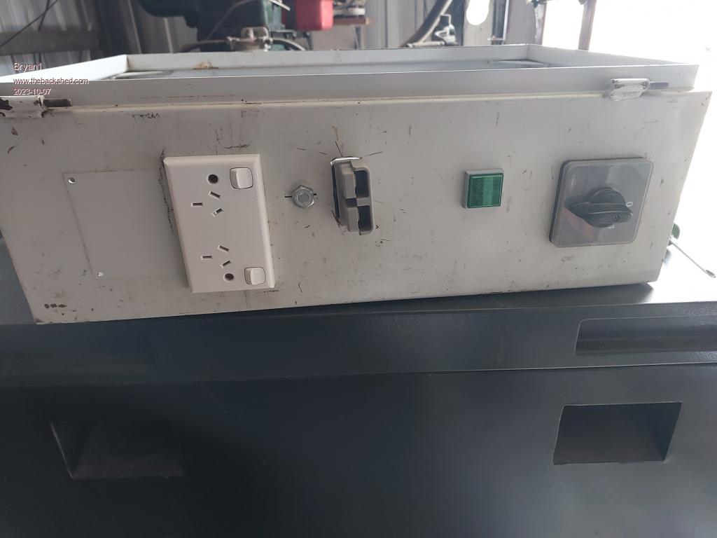 Now I have read before about blowing the fets on turn on so if my thinking is right once the battery is connected it should charge the caps if I'm thinking right. Cheers Bryan Edit: Well got the ground connection sorted and fired up the inverter and first tried my mig where after doing a tack the mig turned off and I saw on the AC gauge the output voltage had dropped to 130 volts then it bounced back to 245 volts and the mig turned on again. So decided to test out my bunnings vacuum and it worked nicely where that gauge showed 2.5 amps drawn. Next I tried my 5" grinder and it worked nicely. Decided to put my current meter on a battery lead and with no load 38 amps  and the toriod was nice and warm where after 10 minute later after it was turned off the temp was 72C. and the toriod was nice and warm where after 10 minute later after it was turned off the temp was 72C.So I do think by using both both windings is the root cause so came down for a look at that toriod pic so I'll go back upto the shed and just red/blue secondary as the AC output and see how it goes. Now the led on the inverter was green but the led on the driver board was red but without any data not sure where that problem lies. O'well the testing goes on and hopefully get that idle current draw down from 912 watts  Edited 2023-10-07 15:17 by Bryan1 |
||||
| Bryan1 Guru Joined: 22/02/2006 Location: AustraliaPosts: 1450 |
G'Day Guy's, Rather than keeping on editing a new post with the results was best Well the current draw on idle is 0.5 amps so around 12-13 watts and mig worked nicely so I'm now spewing I didn't bring my good welding helmet home from work this weekend Ran thru a test with the grinder and vacuum and that 0.5 amp idle current was showing again so I do think time for a beer as my first inverter is finished and working  So for others with the areo sharp toriod just go with secondary output and leave the primary out of circuit. Still got to finish the door and I think I'll put a fan on there to draw out the warm air from the toriod and choke. Now for this choke I haven't tested it with a LCR meter but it's working so I'm happy about that and this choke idea did come from that thread thats close to 80 pages long and off memory it was tony that supplied the pic and description of it. Cheers Bryan |
||||
Revlac Guru Joined: 31/12/2016 Location: AustraliaPosts: 1153 |
It works, now you have something to play with.  I tested the start surge on a few things today that I haven't done before, the Torus saw bench was 4600w and the Planer was 6210w tested with a (surge rated) clamp meter in a box connected to the appliance. Soon will be running these off the Mad inverter instead of the old Axpert HF inverter, should be easy work for the DIY LF Inverter. Cheers Aaron Off The Grid |
||||
| Bryan1 Guru Joined: 22/02/2006 Location: AustraliaPosts: 1450 |
yea the rating on that mig welder is 7.2Kva so I'm impressed this inverter powered it up and just works but I will need to ask my daughter to look at that guage so I can get the readings while the mig is going. My next inverter will be the mad board and having those 360 amp fets will make for one beefy inverter I'm sure. Cheers Bryan |
||||
| wiseguy Guru Joined: 21/06/2018 Location: AustraliaPosts: 1206 |
Good to see your progress Bryan. The 2 x toroids I have are 3.5KW Aerosharps like yours but a subtly slightly different version. The primaries on mine are 230V & 195T the secondary's are 250V & 212T. I intend to remove 17T from the 250V windings, which luckily are the outer winding so I will have 2 secondary's of 230V & in parallel. I calculated that at 5KW load with a single secondary the R losses are ~50W but with the two in parallel it will be ~ 25W. The idling power will not change, just the efficiency (and lower heat produced) under high load. I may have written the turns for the primary and secondary in texta on the outside of your toroid? I'm getting old and it was a long time ago so I don't remember now... So the 17T removed for mine I am sure will be a few turns different for your toroid. I am guessing that having finished the build, the thought of dismantling and unwinding some turns on one winding will not be greeted with a whole lot of enthusiasm ? Edited 2023-10-09 14:00 by wiseguy If at first you dont succeed, I suggest you avoid sky diving.... Cheers Mike |
||||
| Godoh Guru Joined: 26/09/2020 Location: AustraliaPosts: 530 |
Hi Bryan good to hear that you have a working inverter. I read up the page a bit that you had trouble soldering old cable. Often the plastic seems to migrate into the wires. I have found that dipping the end into hydrochloric acid to clean up the cable works well. Just strip a bit back , dip the end into the acid for a short time and wash it off. The cable comes out shiny and easy to solder. Maybe you had the two windings of the transformer hooked up in reverse to each other. Sounds like the high voltage windings may have been fighting each other to have such a massive idle current. Anyway it looks like you have it sorted. I looked at the board you showed on aliexpress, the one ticked was 220 volt 60 hz and 60 volts. I am guessing that is not the actual board you used. Have fun Pete |
||||
| Bryan1 Guru Joined: 22/02/2006 Location: AustraliaPosts: 1450 |
G'Day Guy's, Well with toriods getting harder to find there a heap of old non working 3 phase welders here at work so I'm thinking of stripping one down for a look and the best part plenty of that 6x5mm or even bigger copper wire for making shunts is there for the taking. Now these 3 phase welders have 3 big transformers so by ganging up all 3 and winding a new secondary would make one think of it would be a pretty heavyduty transformer. I will have to get motivated and wind up a secondary for that E-core I got out of that forklift battery charger and give it go with this inverter build. Also I do have that toriod out of the Kipoint inverter which is rated at 3Kw with a 8Kw surge, as it's already wound for 24 volts it should be a drop in replacement. But I like to think something can be done with these old 3 phase welders I now have access too. Cheers Bryan |
||||
| Revlac Guru Joined: 31/12/2016 Location: AustraliaPosts: 1153 |
Most of the 3Phase welders I have are just a large 3Phase transformer, will need to check, I think they can be rewound for single phase but haven't tried it yet. I know they where really Heavy.  See if you can get a photo of em. Edited 2023-10-09 18:22 by Revlac Cheers Aaron Off The Grid |
||||
| Bryan1 Guru Joined: 22/02/2006 Location: AustraliaPosts: 1450 |
Revlac the one I looked at today was a tad hard to get too but with the torch on my phone I got a glimpse and man what looks like a E-core looking like a figure 8 with 2 huge windings on and what looked like a choke was a good 6" high and wound with 2mm approx wire. Now the big core was wound with that big rectangle wire with a winding on each outer leg. There are a heap of them here and 99% are old 3 phase mig welders and big ones at that. The guy thats owns them has asked me to help him setup a off grid home on a property he bought for his retirement and with my first Mad board eh I got 25 of those big fets so may aswell put em all on Now finding a transformer to power that board is where I'm heading with these old welders.I did do a search on the forum for E-core inverter builds and nothing came up but eh nothing ventured nothing gained and after all it is all just plain fun isn't it. Cheers Bryan |
||||
| Bryan1 Guru Joined: 22/02/2006 Location: AustraliaPosts: 1450 |
G'Day Guy's, Well at smoko this morning moved a bit of stuff so I could get some pic's 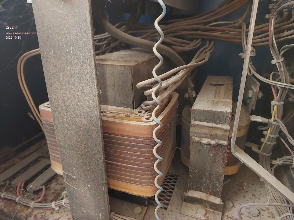 Now the core measure approx 250 high x 300 long and it's 100mm thick and it has the wires on each outer leg of the core. The core is all welded together and it won't take much to grind out the weld to get the windings out. 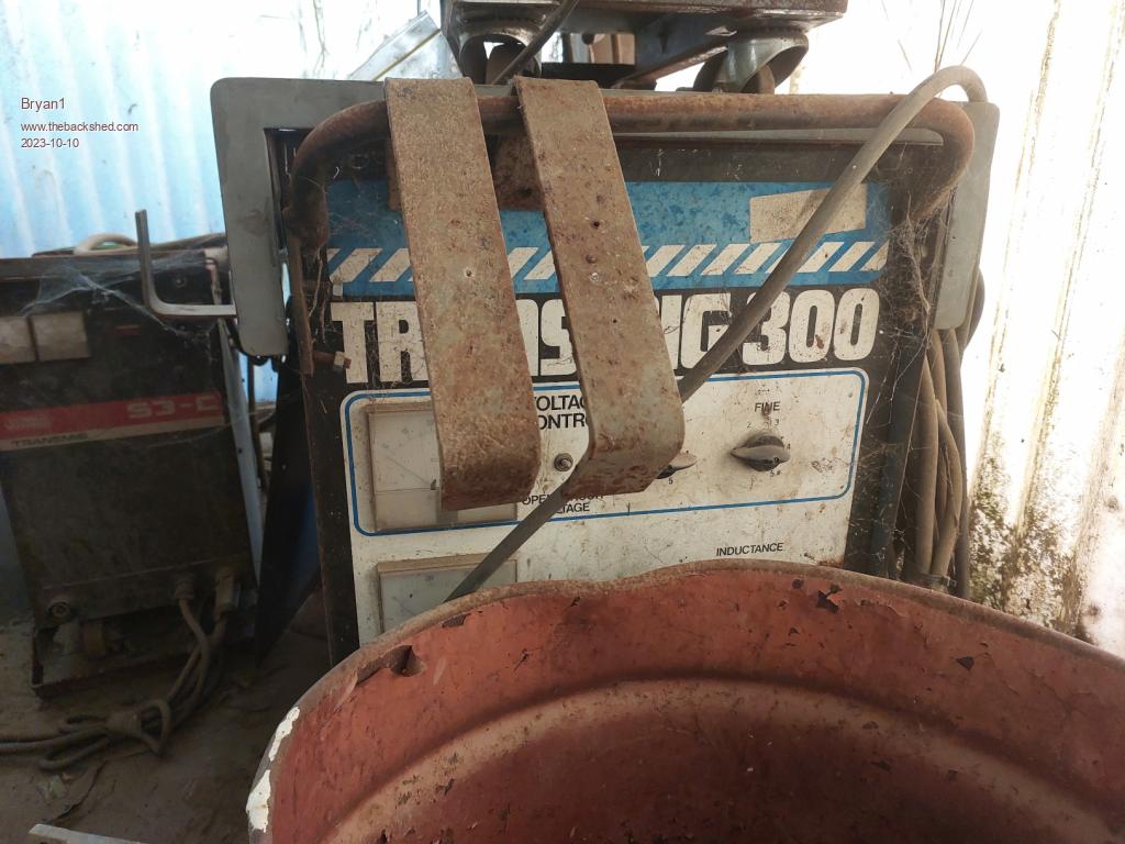 This is the donor Mig welder and plenty of good bits on it too like those 2 huge gauges a 50 volt one and a 300 amp one. Mike yes that toriod I got from you did have the turns written on and to keep all that plastic tape from fraying I wrapped some of my yellow tape to fully cover the toriod. So any hope of taking windings out is gone as it's all sealed up and trying to take the tape will be a nightmare I'm sure. Cheers Bryan |
||||
| rogerdw Guru Joined: 22/10/2019 Location: AustraliaPosts: 904 |
Hi Bryan, what brand of mig welders are they? I recently bought 6 older non working single phase WIA migs for $50 each. Sold first one for $1,100 and 2nd one for $700. Have fixed a 3rd, but seeing how well it works have decided to keep it myself. Have 3 more to fix. And now I have a better idea of their worth, wont sell them too cheap. First one was sold and picked up in less than 12 hrs from posting the ad ... and had a heap of people lined up if it fell through. 2nd one was less desirable, hence much cheaper. Maybe you could resurrect some and sell them ... then use the funds for your solar gear. Cheers, Roger |
||||
| Bryan1 Guru Joined: 22/02/2006 Location: AustraliaPosts: 1450 |
Roger the one pictured is a Transmig 300 and the electronics are cactus, also there are quite a few others in the same condition. I do reckon going with that E-core I already have and that's one you and Mike have seen just to see if the E-core will work as a toriod replacement. A while ago we did work out for that one 300 turns are needed for the secondary and by 1.6mm wire I can go 2 inhand 1.6mm for 6 layers which will still leave plenty of room for the primary. Now I did try to compare my old Kipoint inverter for standby current but with that inverter with no load it just went into fault mode and I did see 0.7 amps before the beeping started. This weekend I'll be putting that new inverter inline for my shed power and I do need to put some round lugs on the end of the 240 volt wire cable that goes to my circuit breaker board so the inverter can hard wired into the shed. Cheers Bryan |
||||
| Godoh Guru Joined: 26/09/2020 Location: AustraliaPosts: 530 |
Bryan it will be very interesting to see what sort of standby current the E core transformers draw. I have an old Powerstar W7 with two E core transformers in it. It is horrible as far as standby current goes. It draws around 100 watts from memory doing nothing. I did try an inductor in series with the transformers but they did not help much. good luck with them Pete |
||||
| KeepIS Guru Joined: 13/10/2014 Location: AustraliaPosts: 1872 |
For what my opinion is worth, you might try measuring the Eddy current loss first. If you can cobble an E Core together without much work to try in the inverter then that would obviously answer the question. In either case you are trying to measure idle current (no load). Every big E-Core I have tested has been horrendous, much the same as Godohs experience, or worse. If you power one of the E cores, as it is, without any secondary load, you should find that after a while the Core becomes quite hot or very hot, that is also a basic indication of power loss (Heat) you will be dealing with at idle in an inverter. NANO Inverter: Full download - Only Hex Ver 8.1Ks |
||||
| Revlac Guru Joined: 31/12/2016 Location: AustraliaPosts: 1153 |
Yes definitely needs testing to find out what the Idle is. The EI transformer inverter I did, was about 20w running as an Inverter, I don't call that Horrendous, I cant find the 230vac idle test but I think it was around 7w give or take abit. As with some ready wound toroids, The same rule also applies to EI transformers, they need more turns added on to get the idle down to a somewhat manageable level (not easy to do if its already assembled and no real estate left) and also needs a good choke, still not near as efficient as a toroid. Edited 2023-10-11 20:25 by Revlac Cheers Aaron Off The Grid |
||||
| The Back Shed's forum code is written, and hosted, in Australia. | © JAQ Software 2025 |
