
|
|
Forum Index : Electronics : Bryan's Inverter build
| Author | Message | ||||
renewableMark Guru Joined: 09/12/2017 Location: AustraliaPosts: 1678 |
Hi Bryan, I don't know if any of this will be useful to you but this was my 24v build. here It's actually sitting in my shed now as it's too heavy for my light weight van I built. Cheers Caveman Mark Off grid eastern Melb |
||||
Bryan1 Guru Joined: 22/02/2006 Location: AustraliaPosts: 1450 |
Thanks Mark your build is a good read mate and it did answer my question of using 35volt 10,000uf caps so in my quest today to get that RS13-1212S chip I got more parts for this inverter. Now Mike did suggest with these HY5608 fets to drop the 10 ohm resistor to 4R7 so with my Altronics order got more parts. For the heat sinks I cut up the Aerosharp one and by cutting off the bottom 2 fins the fets can be connected and the fins facing out from the board. The Brain board is 99% done and just need those 1uf caps along with the fet driver chips and a few more parts. The goal is get my first MTTP up and going then I'll be going head on to this inverter project. I'm slowly getting up the courage to straighten out that 6.5x5mm copper wire and wind the primary on that Aerosharp toriod. rather than use heat shrink I'll just wind some of that yellow tape to isolate each turn. More to come |
||||
| Bryan1 Guru Joined: 22/02/2006 Location: AustraliaPosts: 1450 |
G'Day Guy's, Those 360A fets turned up this morning along with the LCD's and extra nano's  So now just waiting for that digkey package and it's all steaming ahead as this old Kipoint inverter is on it's last legs as the AC voltage regulation is shot and adjustment is needed before I can start my VDF's for machining. Cheers Bryan |
||||
| Bryan1 Guru Joined: 22/02/2006 Location: AustraliaPosts: 1450 |
OK Guy's the grey matter is starting to clear and all I need to finish the component list is a few caps and the fet drivers. With these 360 amp fets I'm going to go 3 each leg just so I can suck the best out of aerosharp toriod as it is rated at 3Kw but as Mike pinted out when he gave it to me he said just connect the existing windings in parallel. Those 10,000uf 35 volt caps do look a tad small to me but Roger did say he used them and I am thinking of trimming down the aerosharp heat sinks so they can inwards as that will solve the fan solution. With my big win on the grey matter over the MTTP it is time to wind this toriod with that 6.5x5 copper wire and 3 metres going over and getting less each time will be a fun task to do. Now for the choke for this inverter I used the big choke out of the aerosharp and wound 10 turns on each side and i have looked a Tony's pic that many times I will know how to get it connected in phase. Cheers Bryan |
||||
| Bryan1 Guru Joined: 22/02/2006 Location: AustraliaPosts: 1450 |
G'Day Guy's, Well I have stepped back after that blown fet display on the MTTP project  Now with my other hobby of moonshining as I'm off the grid I just made my own burner and use LPG for heating. Now the crowd on the grid use elements where 2400 watt and 3600 watt ones are used. So pure restive loads I read have caused problems so I do need to nut that one out as I do want this inverter I make to handle this load. Did a parts count list for parts and $92 plus I still need to source the fet drivers. So plenty of time to think about these issues. Cheers Bryan |
||||
| KeepIS Guru Joined: 13/10/2014 Location: AustraliaPosts: 1872 |
That's actually not the case, pure resistive loads are the easiest load for an Inverter to power. . NANO Inverter: Full download - Only Hex Ver 8.1Ks |
||||
| Bryan1 Guru Joined: 22/02/2006 Location: AustraliaPosts: 1450 |
Thanks mike good to know as I would like my inverter that I imported in '05 to work again. I reckoned I killed it welding up the 2 ovens on the 1850 wood stove project. Going from a Sg of 1024 to 1012 after I finished did show I gave that forklift battery a good run. After I did that my 8" grinder wouldn't work and go overload, I have asked Roger to look at this problem as if he can fix it we can learn how the inverter boards were made before the crowd got onboard. A few years ago I did email Kipoint on a schematic of this board where they said the guy who designed left the company for his own venture so one may say I got the proto type inverter that has standed the test of time. Cheers Bryan Edited 2023-06-17 20:14 by Bryan1 |
||||
| Bryan1 Guru Joined: 22/02/2006 Location: AustraliaPosts: 1450 |
G'Day Guy's, Well as I said in my other thread my man cave/shed is now without power and I'm letting my forklift battery fully charge before taking off the solar. So I've changed tack and started working on the house shed again so I can finally setup my area at the back so I can move all my electronic gear down and make the room for electronics and my cnc. Now as I'm on a lean budget as work aint very much I've decided to build up that ching board I got ages ago. 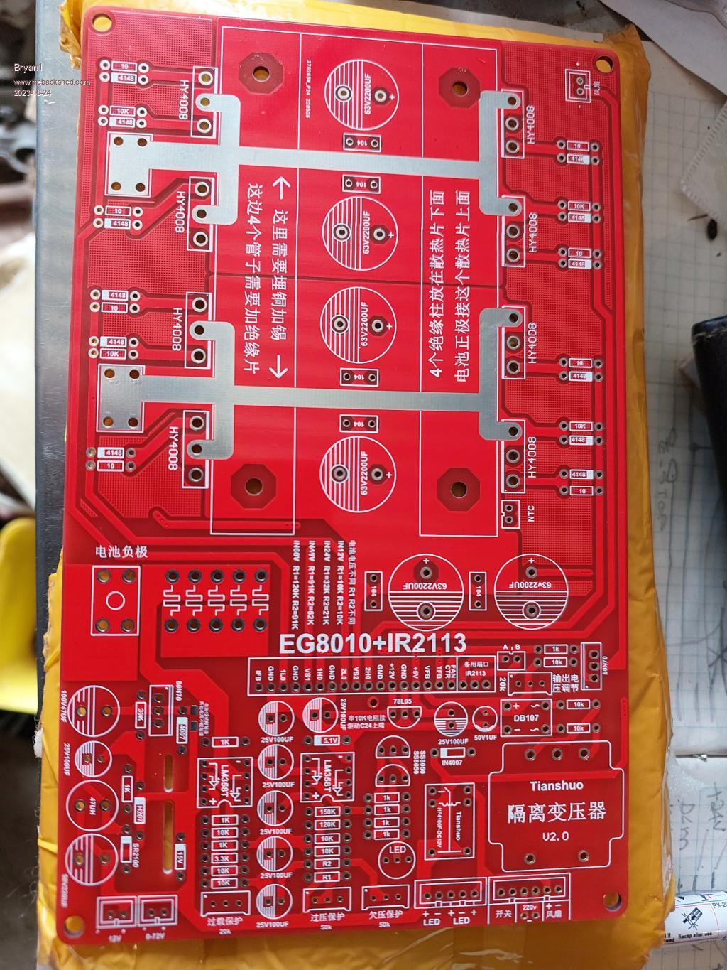 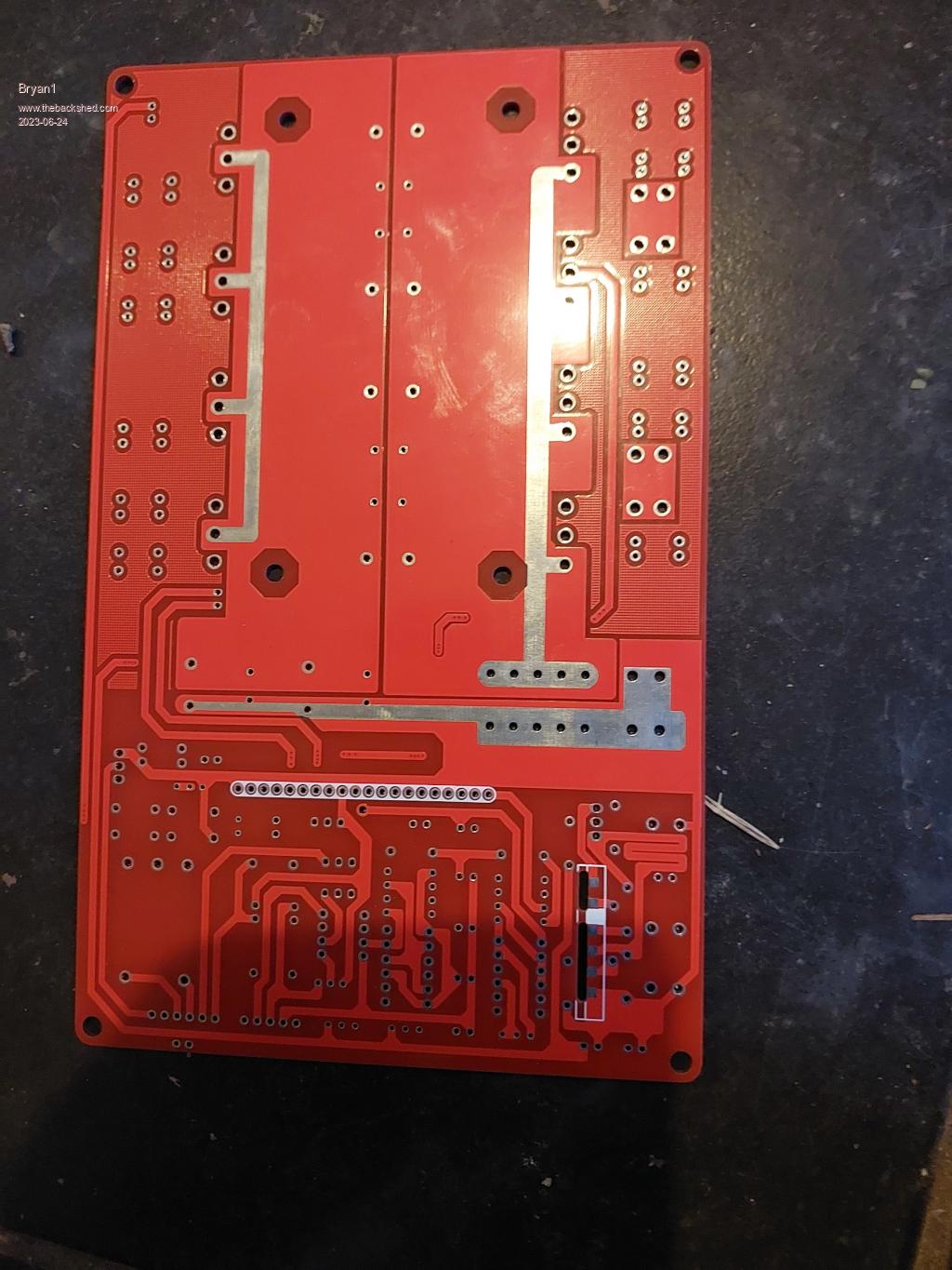 I do have those HY5608 360 amp fets here to use so the fets should get the best out of that 3Kw areosharp toriod. I do have a fair bit of 18sq.mm cable here so I'm going how many turns I can get inhand to fit in the centre of the toriod, I will be going with 12 turns for 24 volts. Also I don't trust those power pcb tracks on the board so I'll put some copper wire on the tracks and solder them on so the current can flow as it needs. Poida put up this schematic which I've been comparing with the circuit board and it is a close match. 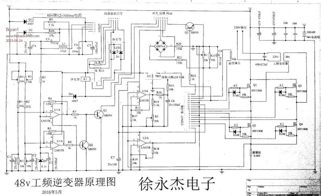 For me understanding what the LM358's are actually doing will go along on my journey to understanding the big picture. Now those step down DC boards that fit vertical on the pcb I still need to find a source and knowing what the step down on the feedback 5 pin transformer. I did order a couple of EGS002 boards and the expected delivery is 13/7 so plenty of time to get my head around this chinese board. Cheers Bryan |
||||
| tinyt Guru Joined: 12/11/2017 Location: United StatesPosts: 441 |
Except for the mosfet and bulk capacitor count that board is similar to what I am working on. I hope you also have the small board that gets soldered to the two oblong slots. In the schematic, U1 and the two trimpots(R3,R4) are use for monitoring battery voltage. And if pin1 and pin2 of the 6-pin connector are connected together, Q1 and Q2 can control the turn on/off of relay K1. If K1 is energized, it applies 12vdc to the 5vdc regulator applying power to the EGS002 board. R4 sets the battery low voltage cutoff and R3 sets the battery high voltage cutoff. So, if the battery voltage is higher than the low cutoff and lower than the high cutoff, K1 will be energized. The lower U2 is for the overcurrent sensing(IFB). I don't know where the upper U2 is used, depends upon where R15 is connected. I hope this helps. Edited 2023-06-25 16:16 by tinyt |
||||
| Bryan1 Guru Joined: 22/02/2006 Location: AustraliaPosts: 1450 |
tinyt thanks for that explanation and it is time have another look now as far as that 5 pin thru board item it is all new to me so finding one or explanation of what it does will go a long way to solving this. Well this arvo I decided to see if I could make some magic smoke  by turning my old shed inverter by turning my old shed inverter To my surprise it went thru one fault then the led's turned green and the power came on. So for this inverter to self heal and work after that violent event last week does go to show what was made back in '04 can still keep working is whats missing in todays products. Down the track this old inverter will need to be reverse engineered as what this guy built off the spec's I gave him goes back way before guy's started making them. I told him don't bother with a lcd as they fail just use led's as they do the same job, now if you remember back in the day KiPoint inverters came out of that order I did and a few years ago I rang KiPoint for a schematic where they said they never made that model. Got a call back the next day where the gal said after he made mine he went into his own business so ebay made him heaps and the guy hasn't been since since. Going off that part number for the relay I managed to grab a couple off Ali for a couple of bucks but that 4 pin transformer on the right of the board came up blank as trying to decipher the ching was beyond me. I do assume it is a 220 volt to 12V tranny and Element 14 did have one but again the price for shipping one adds 5X the cost. So I do hope to find some on Ali soon as that is out of the way. Cheers Bryan Edited 2023-06-25 17:43 by Bryan1 |
||||
| Bryan1 Guru Joined: 22/02/2006 Location: AustraliaPosts: 1450 |
G'day Guy's, Well I've gone with one for my first inverter as it is a cheap solution to learning hands on a new venture. After Monday I will know whether to make my first Mad board a full blown one filling the board with those 360 amp fets and hunting 3 toriods as this will the main power source on the shed I want to build at the back of the farm. Cheers Bryan |
||||
| Bryan1 Guru Joined: 22/02/2006 Location: AustraliaPosts: 1450 |
G'Day Guy's, Finally got around to pulling that 16mm Sq cable that we used to power that 24 volt fridge when it worked and I just did a trial run of 2 inhand 11 turns thru the toriod and it fitted very easily. So is 32 Sq mm enough for the primary winding for a single core aerosharp toriod ? |
||||
| Murphy's friend Guru Joined: 04/10/2019 Location: AustraliaPosts: 671 |
Its more than enough Bryan. I replaced a 90 sq mm dual core primary with 25 sq mm welding cable. That's good for a conservative 100A and that it would only see for very short (startup) times in my set up. Back in the days I started building these inverters bigger was better when it came to primary windings, have since found out that the fat primary can contribute to spectacular blow ups if one is unlucky  . . |
||||
| Bryan1 Guru Joined: 22/02/2006 Location: AustraliaPosts: 1450 |
Thanks for that mate and yes I did learn on joining that blown fet club with my MTTP failed build. So this morning taped the wires together and wound the toriod with 11 turns.  So we now have a toroid in a bucket I do have a couple of drums of Dow Corning Dielectric Tough Gel and as I did get it back in '08 today I finally opened them up and did a trial run to see if this stuff will still set. Well after 6 hours it is starting to set and hopefully in the morning it will be set.Then I'll pot the toriod in the bucket then after it is set cut the bucket down to the height then I can bend up some flat bar for clamping the unit. Cheers Bryan |
||||
| Bryan1 Guru Joined: 22/02/2006 Location: AustraliaPosts: 1450 |
G'Day Guy's, Well that $89 inverter finally arrived from the slow boat from aupost and to my surprise it came fully built with connection info, copper connectors, screws and connections for all the connectors. got a few jobbies to do around the farm then time for some play and see how this board goes. Cheers Bryan |
||||
| Bryan1 Guru Joined: 22/02/2006 Location: AustraliaPosts: 1450 |
G'Day Guy's, Here is pic of the inverter 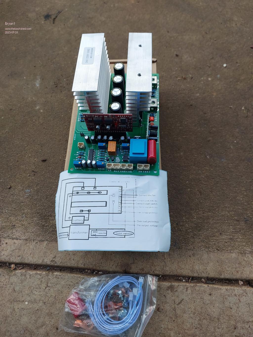 Now with schematic paper shown it is showing the inductor only on one leg to the toriod where I did read putting one on each side was the go. I do have that large aerosharp choke where I wound 10 turns on each side to use so I will go with it. Also I have a couple of those small display boards that connect to the egs8010 board so I'll solder on the header then I can have a display to use to set the pots. Now to left of driver board is a jumper just labelled "J" and one side goes to IFB and on reading the datasheet it should be in place so IFB is tied to ground if my thinking is right. I went in home of 12 volt and they didn't have any 120 amp Anderson connectors so I still need to source one for the battery connection. So no hurry and plenty of more pic's to come as I build this up. For the long term I want wind that huge E-core to use with this board but for now I have that aerosharp toriod to use. Cheers Bryan |
||||
| Godoh Guru Joined: 26/09/2020 Location: AustraliaPosts: 530 |
Have fun with the project Bryan, I have three inverters based on those boards. They all seem to have slight differnces, at least you are fortunate that the connections diagrams came with them. I have rewound powerjack transformers on mine, have run one of them now for a couple of years with no problems. I have another core ready for a total rewind to make a very robust transformer but don't have the wire yet to wind the secondary. Lots of other projects have bumped the transformer rewind down the list. Anderson connectors can be got from battery shops, but I find ebay ones to be the cheapest. Sometimes they are on Gumtree too. I prefer solid lug type connections for inverters myself. But it depends on where and how you are going to use the inverter. Have fun Pete |
||||
| Bryan1 Guru Joined: 22/02/2006 Location: AustraliaPosts: 1450 |
G'Day Guy's, Well got toriod and inductor mounted in that box I showed before and I secured the toriod with 1/4" allthread with some silicon hose over the thread to isolate and bolted down with some 16mm MDF. I managed to put a 25 sqmm lug onto the primary outputs and I do think 1 off 16sqmm cable should be right for the connection to the board. If the cable does get warm I'll change it over to some 25sqmm wire. Still got to put a cover over the hole in the back of the box so the inverter can be mounted and with using the Anderson connector it will be easy to connect to my shed battery and the old house battery as that is the connector I use on my system. That small screen I have will see me thru the setting up and I do need to source the volt meter displays so finding the right ones may prove some fun or I may just lucky. Cheers Bryan |
||||
| Bryan1 Guru Joined: 22/02/2006 Location: AustraliaPosts: 1450 |
Went into the 12 volt shop this morning and got the Anderson connector and they nothing in the way of decent terminal blocks so as I do have a heap of those M4 pcb connectors and a heap of circuit board I'll get busy with the dremmel and make my own. That way mounting the AC cap will be easy and I'll have hard wiring connection points aswell as a dual 240 socket. got onto fleabay last night and found a AC volt meter with a hall effect sensor ring for current 100 amp, so putting the current ring on the primary should let me see the primary current. Cheers Bryan |
||||
| Bryan1 Guru Joined: 22/02/2006 Location: AustraliaPosts: 1450 |
Well getting there with the build, now when Mike gave me this toriod he did say the primary and secondary can be put in parallel. 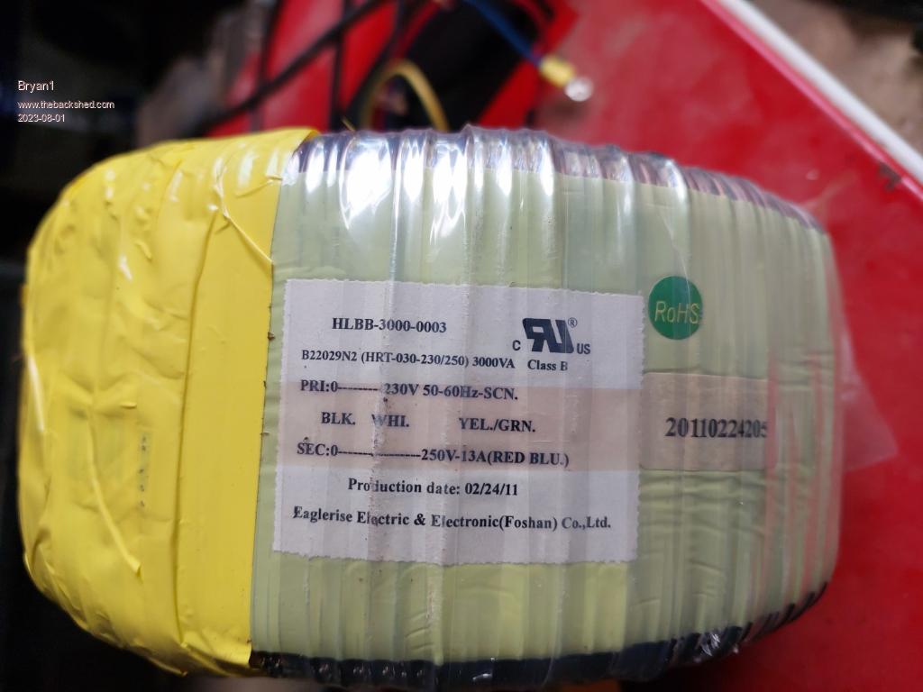 Now going off that info I put black and red together and blue and white on the other leg. So my question is is that the right combo as I do want to get this right also which side of the output become active and neutral ? Cheers Bryan |
||||
| The Back Shed's forum code is written, and hosted, in Australia. | © JAQ Software 2025 |
