
|
|
Forum Index : Electronics : Bryan's 150V 45 A MTTP
| Author | Message | ||||
| poida Guru Joined: 02/02/2017 Location: AustraliaPosts: 1392 |
R1 is the current limit for the 5V drive from the Nano PWM output into the TLP250 input (LED) Maybe remove the TLP250 and see if there is any pulse, at 20kHz approx., on either end of R1. If there is when TLP250 is removed and there is zero when TLP250 is installed then the TLP250 is suspect. No pulse with TLP250 removed suggests the nano is toast. But the R1( 620R ) resistor should have a signal on the nano or 10 pin connector side, referenced to ground. R1 limits current to about 8mA so it is well within the drive of a nano pin. The display you showed above with "MPPT46 29.3V 10 " means its in mppt mode, 46 seconds into the 60 second cycle where it checks again for a reason to go into mppt mode and the 10 means the PWM pulse with is 10 cycles wide. 10 cycles is about .62 microsecond and should be easy to see on the oscilloscope Edited 2023-06-10 19:45 by poida wronger than a phone book full of wrong phone numbers |
||||
Bryan1 Guru Joined: 22/02/2006 Location: AustraliaPosts: 1215 |
Thanks for that poida and I'll do that first thing in the morning, now one thing I did notice probing that 5K resistor on the brainboard it was at gnd or close to it and it was in MTTP mode. So if that test with the TLP250 out of socket I'll solder up a new nano and give that a go. |
||||
| poida Guru Joined: 02/02/2017 Location: AustraliaPosts: 1392 |
I do not like seeing -1.0 Amps on either input or output. The direction we apply current to the sensor when calibrating is important. Please confirm both sensors are giving reasonable (not so important to be accurate) readings. So I think it's time to check them again... sorry. And yet another thing to look at are the temperature sensors. The complications of this area are a hangover from me trying to handle both Nick's board and Wiseguy's board. I think the 55C is a problem and it needs to be addressed. We can for now remove any impact these wrong temperature values will have in the running of the program. (once the temps are correct we change to more useful and safe vales) The throttling of output function is always active and when using default values will start to reduce output current LIMIT from the max current limit defined by "L" in the menu, usually 45 Amps and will progressively take this limit down to ZERO when the heatisnk gets to 65C to be sure, do this too: 6 - BV tempco set it to 0.0 this removes any modification of the charge voltage due to battery temperature wronger than a phone book full of wrong phone numbers |
||||
| Bryan1 Guru Joined: 22/02/2006 Location: AustraliaPosts: 1215 |
poida pin 3 on the ACS754 sensors were 2.458 volts and within 0.01 volt of each other, now the temp sensor i'm using came off a old battery charger as I had it onhand. In the morning after doing the test with the TPL250 out of socket will let me know if the nano is toast and I'll put another in with the new code and start from scratch with the calibration. |
||||
| Ziki_the Newbie Joined: 13/04/2023 Location: YugoslaviaPosts: 28 |
@Briyan1 2.458V if no current flow, then you set that as 0A. Maybe for temp sensor you can use trimpot and adj.to mppt readings at 30c(just for test purpose).  Pozdrav iz Srbije |
||||
| Bryan1 Guru Joined: 22/02/2006 Location: AustraliaPosts: 1215 |
G'Day Guy's, Went over to Rodger's this morning to help me out getting this MTTP working. The track going to the TLP250 was gone and with that cap blowing would of been the cause. Then we noticed the R13-12-12 chip was a bit wobbly and found the third pin had come a drift and Rodger put some legs on a smd chip to fix the problem. We tested that choke I made and it came out at 51.7uh so not bad for a first attempt. We also used a new nano and the old nano got loaded with the serial LCD code for Rodger to play with. We had a look on the scope at the fet drive chip and saw some low activity then ramp up so the soft start looks like it was working. We set it up with 2 solar panels and a couple of car batteries in series, calibrated the sensors and the voltages and when a glimpse of sun came it was working So got home and connected it up 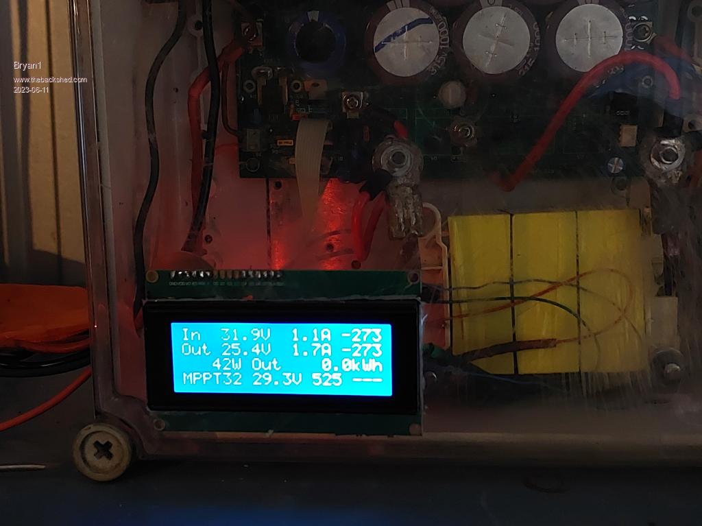 I do need to get a couple of 10K NTC's so the temp is open circuit for now, So where do the fans connect as no connections appear to be on the board. Cheers Bryan Edited 2023-06-11 16:46 by Bryan1 |
||||
disco4now Guru Joined: 18/12/2014 Location: AustraliaPosts: 844 |
Hi Bryan, I think its designed to work without a fan, the output is throttled back if the heatsink gets passed the temperature you set. However it looks like pin A5 is set up to switch a fan on but would need a external driver (FET) added as its only logic level out. A5 comes out on header 1 next to A4 which is the serial out to the LCD. Latest F4 Latest H7 |
||||
| Murphy's friend Guru Joined: 04/10/2019 Location: AustraliaPosts: 602 |
There are plenty of cheap 12v fan controllers on ebay. I prefer using these as it,s much easier (for me  ) to set or change the temperatures the fan is to cycle at. ) to set or change the temperatures the fan is to cycle at.As disco says, no fan needed if your heat sink is big enough but I needed a small fan on mine to blow on the choke when the MPPT was charging at 2.2KW (48V battery bank). |
||||
| Bryan1 Guru Joined: 22/02/2006 Location: AustraliaPosts: 1215 |
Rodger did bring out a decade wheel and dialed in 10K and the temp on the lcd did show the current temp, now a tool like that is going to make it's way into my toolbox. Then I can just use a led and resistor to see when A5 goes high while warming up the heatsink with my blow torch , just running lpg in the torch I decanted from a bbq bottle. Now it got me thinking about making a display and controller for my 20 year old 80 watt shed radio array. It's got 2 off car batteries in parallel I'm keeping alive which is also the voltage input to the MTTP board. Got plenty of fets and caps and making inductors is my thing after reading that uH figure today so to learn and use these fets time for me to learn to code again. I do have a heap of 8 bit pic's that will do the job and have a few books on using assembly code where W is the king.Time for me to see how microchip and linux go with my pickit3. Cheers Bryan |
||||
| Bryan1 Guru Joined: 22/02/2006 Location: AustraliaPosts: 1215 |
Well guy's started the MTTP up this morning and after the slow start CABOOM number 5 fet put on a nice dying show with red hot patch's and filling the box with smoke. 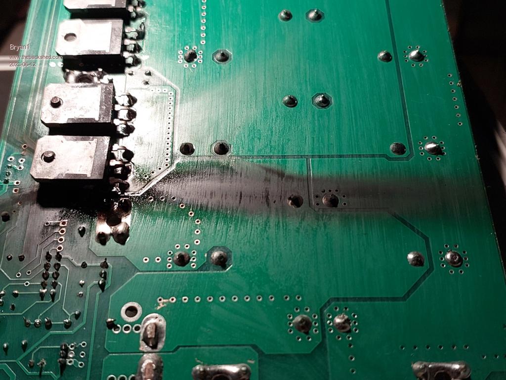 Now this should get me into the blown fet club 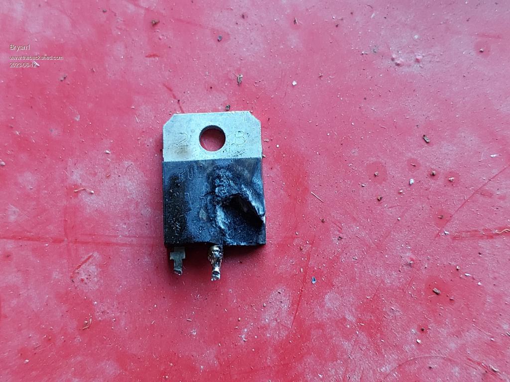 The board is toast so I'll order all new parts for the next build. |
||||
| rogerdw Guru Joined: 22/10/2019 Location: AustraliaPosts: 816 |
Well that's a bit disappointing Bryan, after yesterdays effort I thought you were home and hosed. What configuration of panels were you using at the time ... and did you see what voltages and current were showing before the bang? And I wouldn't write it off yet either ... that damage doesn't look too bad to me, unless the other side is all burned. Give it a bit of a clean with acetone or even metho ... most of that black will buff out.  This is a proper burn up ... new board $8,000!!! 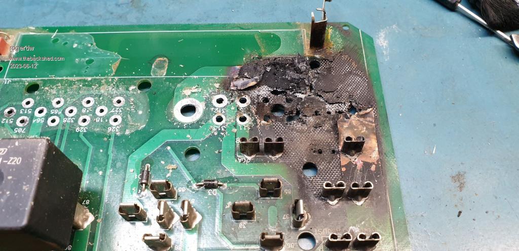 Cheers, Roger |
||||
| Bryan1 Guru Joined: 22/02/2006 Location: AustraliaPosts: 1215 |
Roger when I turned it on it was only showing 1 amp coming in then it slowly ramped up and when the incoming amps hit 8 amps it went bang, no scoring on the heatsink so it didn't short out on that. I set it up on my 12 volt array only to find no amps coming in but the mttp was showing on the LCD. Now when I probed that 4.7K resistor under the nano zero volts was shown so I soldered up a new nano and found it was the same no output on that resistor. I did find a TLP250 at my feet so I put that in but still no voltages going or any activity. So i do think this board is toast as the pads on fet 5 are all stuffed. |
||||
Revlac Guru Joined: 31/12/2016 Location: AustraliaPosts: 964 |
Would have expected the fet next to it to be burnt as well, but it looks untouched why? something else is going on. Edited 2023-06-12 21:09 by Revlac Cheers Aaron Off The Grid |
||||
| Ziki_the Newbie Joined: 13/04/2023 Location: YugoslaviaPosts: 28 |
Are the fets same? What fet Buz...? Pozdrav iz Srbije |
||||
| rogerdw Guru Joined: 22/10/2019 Location: AustraliaPosts: 816 |
Pretty sure they are all BUZ341 ... 200V 33A 170W 70mOhms Cheers, Roger |
||||
| Bryan1 Guru Joined: 22/02/2006 Location: AustraliaPosts: 1215 |
Well Guy's as this is all part of my 20 year upgrade with the build of these 2 MPPT's to suit these 2 solar array's I got which will have to go in separate as combined in full sun they should produce more than 50 amps. Now as I did get the grid tie inverters with the panels those box's are going to be used for each MPPT. Now as each box does have a MC-4 connector I'll use that for the input of the solar and just use some cable glands for the wires on the output where holes are already drilled to suit the glands. The original mounts for the fets in the grid tie was metal clamps to clamp down on the chips so those clamps will do to secure the board making no need to use M3 screws so therefore taking away the risk of shorts  Yes I have been there... Yes I have been there...Now I've always thought as we are using low voltage DC there must be away to get the 12 volts we need to power the boards. Sitting in the outhouse reading my old silicon chip mag's I came across this circuit. 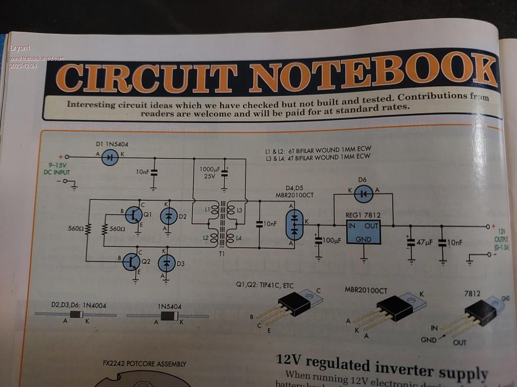 Now for me on 24 volts I reckon I could build that keeping the 6 to 4 ratio, now for guy's on 48 volts the ratio must be changed to suit I do think as it's all about keeping that 12 volt regulator within the spec's. Tomorrow I'll bread board this up using BC337 tranny's and I did find a dual diode chip as the donor chip as the rectifier. Now the input will be taken from the battery side I can't see any issues but eh I'm a hardware type of guy and just love working with copper. When I did the order for all the parts man working night shift does does play a hard game and I ended up buying a 200 volt 60amp single diode. Now as the MPPT does use a fet as the diode I did check with my fluke 365 meter and I answered my own question the diode has a 0.3 voltage drop and facing down as it will be on the board the right leg will be bent to suit the centre pin( drain) on the pcb. I did end up 31 caps ranging from 390uf to 1000uf and each cap does need to be tested with my fluke meter to check they are OK. Now with me playing with all this again a new scope tip for my old Gould CRO will costly and seeing all you guy's showing scope pic's which is the best scope to buy and remember I did win$ucks close to decade ago. Cheers Bryan |
||||
| Murphy's friend Guru Joined: 04/10/2019 Location: AustraliaPosts: 602 |
Bryan, it would be way cheaper to use a commercial DC/DC buck converter for this job. I'm using one, they are small, reliable and there are hundreds to choose from. That article is possible many years old, when those modular DC/DC converters were not thought of yet. |
||||
| phil99 Guru Joined: 11/02/2018 Location: AustraliaPosts: 1815 |
That circuit is a Boost Converter, the secondary volts are added to the input. The input to the 7812 will be about 60% higher than the supply. If you want 12V just use the 7812. Better still is the above suggestion. Much more efficient. |
||||
| rogerdw Guru Joined: 22/10/2019 Location: AustraliaPosts: 816 |
Hi Bryan, I'm with Klaus and Phil ... it would be much easier to use one of the cheapie DC-DC converters. I can help you out ... I have a couple spare ones here you can have ... 1A High-Voltage DC-DC Converter DC 10-80V to 12V You should still have my number, otherwise send me a pm. Merry Christmas. .jpg) Cheers, Roger |
||||
| InPhase Senior Member Joined: 15/12/2020 Location: United StatesPosts: 178 |
A slight modification to the secondary winding of that circuit would make it fully isolated from the primary and suitable for high side FET driving. |
||||
