
|
|
Forum Index : Windmills : Yet another axial
| Author | Message | ||||
Rastus Guru Joined: 29/10/2010 Location: AustraliaPosts: 301 |
Hi Glenn, I may have missed the point altogether here but wouldn't you have tested the air gap and output to find the highest output having anticipated the mill to run cooler from the outset.So if you have 1.54vp-p with a close coil position(looked very close 3mm?)and allowing for runout,wouldn't it be possible to have minnimal gap without problems?The test certainly looked like it had some pace.Well done! Cheers Rastus see Rastus graduate advise generously |
||||
| Gizmo Admin Group Joined: 05/06/2004 Location: AustraliaPosts: 5019 |
OK the figures. A 12v system, reaching cut in speed at approx 170rpm. Wires gauges used are 18(1.03mm), 16(1.3mm) and 14(1.65mm). There is 160mm of wire per turn average. I used the resistance figures on this page http://www.thebackshed.com/Windmill/Docs/WireSizes.asp Magnet Stator V per Turns Wire Turns Ohms Ohms phase Gap Width turn 2.5v Gauge fitted coil (star) 9 7 0.0452 55 18 77 0.263 2.104 16 45 0.096 0.768 11 9 0.0408 61 16 59 0.126 1.008 14 12 0.0366 68 16 78 0.167 1.336 14 50 0.067 0.536 18 16 0.0298 84 16 104 0.223 1.784 14 64 0.086 0.688 21 19 0.0276 90 16 123 0.264 2.112 14 76 0.102 0.816 27 25 0.0228 110 16 162 0.347 2.776 14 101 0.136 1.088 The 11mm gap, 9mm stator makes the best use of coil winding space for 16 gauge, so didn't try 14 or 18 gauge. All the other readings were either too high or to low. If I only wind 68 turns of 16 gauge wire into the 14mm gap 12mm stator, I get a resistance of 0.145 per coil, better but still not as good as the 9mm stator. Cost of the copper needs to be considered too. The increased output when I moved the coil to one side was due to the increase in flux closer to the magnet. I averaged the readings in the end, ie, if I get 1.5 near the magnets and 1.2 in the middle, I used (1.5+1.2+1.5)/3 Now I should do a set of calculations for 24 volts, but I'm tired with typing numbers into my calcualtor, so later. Glenn Just adding, voltages readings are peak, measured with a CRO. If I used a multimeter I would need to multiply the readings by 1.414, as most multimeters read AC in RMS, not peak. The best time to plant a tree was twenty years ago, the second best time is right now. JAQ |
||||
| Gizmo Admin Group Joined: 05/06/2004 Location: AustraliaPosts: 5019 |
I'm puting together a excel spread sheet to help with the maths. As I'm using 4 coils per star leg, I might find wiring the coils with thiner wire for higher voltage will make better use the the coil space available, and divide it down. Example, if I find a good wire size for a 48 volt system, then 48 divided by 2 or 4 gives me 24 and 12 volt options for the same stator. Glenn The best time to plant a tree was twenty years ago, the second best time is right now. JAQ |
||||
mac46 Guru Joined: 07/02/2008 Location: United StatesPosts: 412 |
Hello Glenn, Thanks for the updates and a good idea on the higher voltage coils, its looking like this may be the best way to proceed. Still not to terribly disapointing, I was generally surprised at the readings...Keep up the good work. ...Mac46 I'm just a farmer |
||||
| WattsUp Newbie Joined: 15/07/2011 Location: United StatesPosts: 2 |
This is a very interesting thread. Great work Gizmo. I am not sure if I should put this in its own thread or post it here because my project sort of mimics the one in this thread? I am starting a very similar project and I have a few questions. To make it simple this is what I have (I got it for free so this is what I am using): 1. 12 pieces of grade 8 ceramic magnets that measure 2 inch x 2.8 inch x 1.1 inch thick. Yes, these are big suckers and weigh about 1 pound each. I want to give this a go but I want make sure what I am trying is not destined for failure. Here are my questions. Hopefully one of the experts here can tell me if this is OK to do. 1. Most of the Hugh Piggot style axial flux generators, have two magnet discs. One in front of the stator and one behind the stator. Can I get away with using just ONE magentic disc in front of the stator? I would be using the twelve ceramic magnets listed above on this disc. Does the double magnetic rotor design provide a significant increase in power? 2. I plan on making the stator following Hugh Piggott's 9 coil, 3-phase stator. With my 12 magnets on just one steel plate, how many turns of copper should I do for each coil? I want to charge a 24 volt battery bank. I was thinking around 100 turns of 16 AWG but I don't know? Or should I wind more coils (e.g 12 coils, 15 coils, etc)? I don't know what is better? 3. I am hoping for about 500 Watts in 25 mph wind. Is this achievable with what I have or am I dreaming? Thanks in advance for any help or suggestions! I know that these are not simple questions. I do appreciate anybody who takes the time out of their busy schedule to help me out. |
||||
| WattsUp Newbie Joined: 15/07/2011 Location: United StatesPosts: 2 |
One thing I would like to add. There is a surplus store here in town that has over one hundred 2in x 1in x 0.375in thick grade 8 ceramic magnets. They are only 30 cents USD each! Would I be better off using as many as these as I could fit on the outer rim of a 12 inch diameter steel disc? I would be willing to try both ideas if they both have the possibilty of providing decent results. |
||||
| Gizmo Admin Group Joined: 05/06/2004 Location: AustraliaPosts: 5019 |
Hi WattsUp Having the magnets on bith sides of the stator is pretty important, especially for low power ceramic magnets. I'm not sure but I would say it would be close to double the power. With magnets on one side only there is nothing to drag the flux lines across the gap and through the stator coils, the flux lines will be making for the closest magnet, which in your case is next door. But you can still get reasonable power by adding some iron behind the stator. The iron will attract the flux lines through the stator, improving power. Have a look at a alternator Ed Lenz built with one magnet disc http://www.windstuffnow.com/main/alt_from_scratch.htm Your second question, you need to wind a test coil and spin the alternator up to see what voltages you can get per turn. Its the only way to work out coil turn numbers. Last question, sorry, no idea. A lot of work was done with ceramics many years ago, but not much of the info from then is available. Neo magnets have been the prefered magnet for some time, but with the price rises, there is a new interest in ceramic's Glenn The best time to plant a tree was twenty years ago, the second best time is right now. JAQ |
||||
| Xmaswiz Regular Member Joined: 14/04/2011 Location: United StatesPosts: 69 |
you might be able to just add a second rotor plate behind the stator minus the magnets, it should draw enough of the mag flux lines to keep it reasonably directed, if you can get the extra magnets you may as well make a dual rotor. Santa Maria, CA. Noel |
||||
| Gizmo Admin Group Joined: 05/06/2004 Location: AustraliaPosts: 5019 |
Yeah thats a good tip Noel, the 2nd plate. A plate that rotates with the magnet plate will have virtually no eddy curreny losses compared to fixed iron. Glenn The best time to plant a tree was twenty years ago, the second best time is right now. JAQ |
||||
| Xmaswiz Regular Member Joined: 14/04/2011 Location: United StatesPosts: 69 |
I have wondered if a rotor of magenets/ no steel, locked in resin (center) with 2 stators, followed by a back plate rotor on the far side of the stators would be as efficient as a dual mag rotor, saving on the mag costs, and using just a thick enough rotor plates to draw the flux lines directly above and below. any thought on that would be very welcome. Santa Maria, CA. Noel |
||||
| Gizmo Admin Group Joined: 05/06/2004 Location: AustraliaPosts: 5019 |
I think its possible, but there may be some problems in real life. Keeping the magnets in place for one, they do a lot of vibrating when the alternator is working hard. Locked into a aluminium center might work better, since there would be no eddy currents as the magnets are fixed in reation to the aluminum. Also the cost of copper might outweigh the savings in magnets. Dunno, I think its worth looking into. Glenn The best time to plant a tree was twenty years ago, the second best time is right now. JAQ |
||||
| electrondady1 Senior Member Joined: 12/02/2009 Location: CanadaPosts: 208 |
wattsup i would buy every one of those 100 magnets at the surplus store and use them for the second rotor. use three mags per pole (2x3) to give a good match to the first (2x2.8) you would have enough to stack them up two mags thick and still have enough for another alternator. make the steel rotors wide enough so that your mags are farther apart on the rotors(mag spacing) than they are from one mag rotor to the other.(mag clearance or air gap) that way, the magnetic flux is coaxed to cross through your coils. when i do a test coil i just use one rotor. what ever the output, the second rotor will double it Xmaswiz i tried building them as you describe, but realized your are producing 1/2 the magnetic flux density and using twice the copper to capture it. |
||||
| Gizmo Admin Group Joined: 05/06/2004 Location: AustraliaPosts: 5019 |
Some more work towards the axial today. I want to try a few idea's on this thing, one was to use my CNC router to make the stator mold. After sorting a few bugs out of the CNC, today I finally did something useful with it and made a half scale mold. I wanted to test the g-code before letting the machine loose on some 25mm thick MDF. 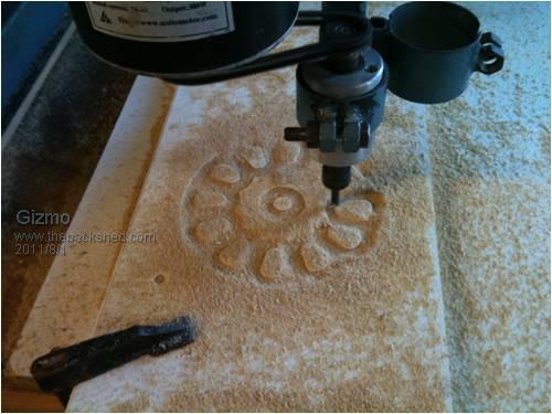

This one is only a few mm deep, the real one will be 10mm deep at the coils and 16mm deep at the mounting ( center ). The center of the coils is left raised to help position the coils precisely. Its only a low power alternator, and the coils will be embedded with epoxy, so I can leave the holes in the stator I think without it loosing too much strength. Glenn The best time to plant a tree was twenty years ago, the second best time is right now. JAQ |
||||
| brucedownunder2 Guru Joined: 14/09/2005 Location: AustraliaPosts: 1548 |
Nice work Glenn. You are a very clever person .. I look forward to seeing what forum guys get up to, just amazes me the talent that abounds on this forum. Ps , haven't sourced a plug for that internet dongle yet - getaroundtoit soon. Ilda finally arrived home,2 days delayed in Santiago. Tracker going nicely Bruce Bushboy |
||||
| Gizmo Admin Group Joined: 05/06/2004 Location: AustraliaPosts: 5019 |
Ordered some wire today, should have it tomorrow or next Monday. Originally I had planned to use 1.15mm wire to give me 72 turns per coil for 2.5volts, for a 12v system The 1.15mm copper has a area of 1.04mm2 Rethinking it, I've decided to use 0.91mm wire. I'll get 132 turns in the same space, and almost double the voltage. I have 4 coils per leg, so I can run them in series for 24v and in series parallel for 12v. The cross section of two 0.91mm wires in parallel is 1.3mm2, so I'm not going to loose any current capability. I'll bring the wires for each coil out of the stator mould. A bit messy but means I can tinker with the configuration. Need approx 260m of wire, which works out to about 1.4kg Glenn The best time to plant a tree was twenty years ago, the second best time is right now. JAQ |
||||
| mac46 Guru Joined: 07/02/2008 Location: United StatesPosts: 412 |
Gizmo, Hello Glen, I suppose about now you'r makeing coils, maybe even pouring the resin. Good luck with you'r project, looking forward to see how it turns out. Good thinking about the series run for 24 volt/ series,parell for 12 volt with the thiner wire @132 turns...I"m thinking this will be a 3-phase machine, is this correct? with kind reguards...Mac46 I'm just a farmer |
||||
| Gizmo Admin Group Joined: 05/06/2004 Location: AustraliaPosts: 5019 |
Hi Mac Nah, copper wasn't ready to pick up, Monday hopefully. Thats OK, I have a busy weekend anyway. Yes its going to be a 3 phase machine. Glenn The best time to plant a tree was twenty years ago, the second best time is right now. JAQ |
||||
| Gizmo Admin Group Joined: 05/06/2004 Location: AustraliaPosts: 5019 |
Just an update. Picked up the copper, and started winding coils. Used the CNC to make some coil formers. 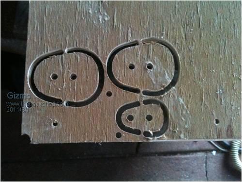
This is the wire tensioner, it works brilliantly! 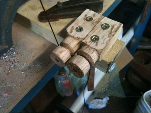
Phills suggestion, make some little paint brushes for laying down the epoxy as I wind the coils. I found some twigs in the yard and hairs from a old paint brush. 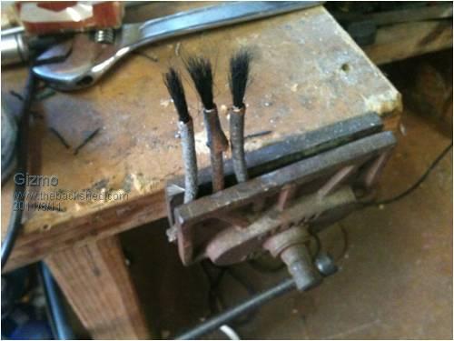
Winding the first coil. I ended up using the lathe to support the coil former. 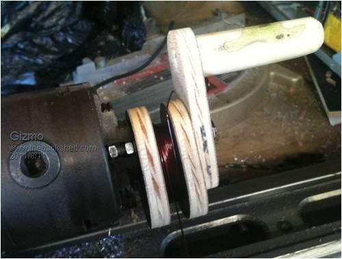
After winding, each coil is allowed to cure, about 12 hours. 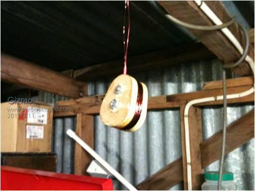
Finished coil. 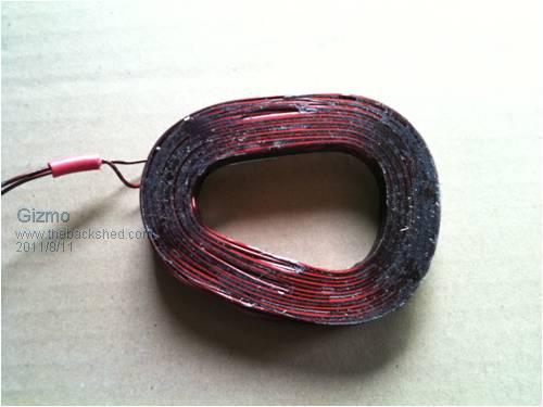
Each coils has 140 turns of 0.9mm wire. Its a tight squeeze, in hindsight I think it would have been a lot easier to use 0.8mm wire, but this would mean less power in the end. I've only got 3 formers, so it will take a couple of days to make all 12 coils. Glenn The best time to plant a tree was twenty years ago, the second best time is right now. JAQ |
||||
| Rastus Guru Joined: 29/10/2010 Location: AustraliaPosts: 301 |
Hi Glenn, Top marks for the tight,evenly wound coils!Jealous of how usefull the CNC is as well,Cheers Rastus see Rastus graduate advise generously |
||||
| mac46 Guru Joined: 07/02/2008 Location: United StatesPosts: 412 |
Hi Glen, There is alot of good suggestions and ideas in you'r post. I like the way the coils are very tight and uniform in size/shape to each other. As I understand it, all coils will be wound the same direction, is this correct? And about the epoxy, is this the same stuff used by manufactures of electic motors? Sorry to bother you with a million questions. Everything looks top notch and very proffesional, good work Glen. Kind reguards...Mac46 I'm just a farmer |
||||
