
|
|
Forum Index : Microcontroller and PC projects : HC-12 Wireless Serial Module
| Author | Message | ||||
Grogster Admin Group Joined: 31/12/2012 Location: New ZealandPosts: 9066 |
I would expect so. If the clones seem to be 30dB down on what they should be at full output power, then I fully expect them to be down by a proportional amount at 25mW. We'd need to measure one. Ross has access to a much sexier spectrum analyser at the moment, so perhaps if he reads this message he could do the forums a favour and do a test of clone and genuine at 25mW output..... Smoke makes things work. When the smoke gets out, it stops! |
||||
| RossW Guru Joined: 25/02/2006 Location: AustraliaPosts: 495 |
I tested over the whole range. At P8 it was -30dBm (instead of +20dBm) At P5 it was around -35dBm At P1 it was around -40dBm So the attenuation of output was non-linear but followed more or less along the line of being "less, even less, even less again". |
||||
| robert.rozee Guru Joined: 31/12/2012 Location: New ZealandPosts: 2290 |
has anyone tried simply checking voltage levels at various locations and metering parts between good and bad modules? given that the the off-frequency problem is caused by a dud component (the crystal), the low power could similarly be caused by a single component being wrong - perhaps a 100r resistor where there should be a 100k part, or 100pf capacitor instead of a 100nf one. bear in mind that most stuff out of china is built with minimizing cost as the prime directive; clone makers may well source parts from pretty dodgy sources, for example recycles ceramic caps. cheers, rob :-) |
||||
| Grogster Admin Group Joined: 31/12/2012 Location: New ZealandPosts: 9066 |
Quite probably, but no schematic actually exists publicly on the web that I could ever find. Please prove me wrong. You could reverse-engineer a schematic by disassembling one part-by-part with the aid of a multimeter with a capacitor testing feature, but who wants to bother considering the cost of the things.  I COMPLETELY agree with you on your cloner comments re: dodgy parts. Where the cloners are concerned, every single cent matters. Every fraction of a cent matters. They are built to absolutely rock-bottom prices, so they can sell them cheaper then the genuine one, yet sill make a profit on them. I have no doubt at all, that totally sub-standard parts are used. We already know about the crystal being sub-standard on the clones, so I fully expect that the other passives could well be factory rejects picked out of the scrap bin and used.  Smoke makes things work. When the smoke gets out, it stops! |
||||
| robert.rozee Guru Joined: 31/12/2012 Location: New ZealandPosts: 2290 |
no need for a schematic, just two modules (one genuine, one clone). and you don't need to remove any parts, what is of interest is differences measured in-situ. 1. using a multimeter set to ohms, check from ground to each end of each passive, swapping back and forth between modules as you proceed from part to part. you are looking for a significantly different reading between the same point on the two modules. 2. if this doesn't throw up anything, then repeat metering across each resistor, again swapping back and forth looking for any part that meters different to the corresponding part on the other module. 3,4. again, if nothing is found repeat the above two steps checking capacitances. 5,6. finally, power up and configure the two modules the same, feed a continuous data stream into each, and check the DC voltage at each pad, looking for differences between the modules. if this doesn't produce anything interesting, repeat using a scope on each pad - we know that at the very least there is a difference on the antenna output connection! the resistance and capacitance checks shouldn't take too long to complete, perhaps half an hour, and i suspect will show up something. i'd do it myself, but have everything packed away at the moment, plus i don't have any clone modules. cheers, rob :-) |
||||
CircuitGizmos Guru Joined: 08/09/2011 Location: United StatesPosts: 1421 |
I don't doubt that I have counterfeit modules, so I should probably get some genuine modules to work with. In documenting my CGUSBMULTI module I have some modules with the spiral antenna on the top side of the module, and some with the antenna on the bottom of the module. I don't think that this should make any difference, but I was wondering what Ross/Grogs/others might think of that. 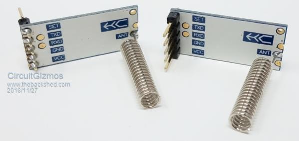  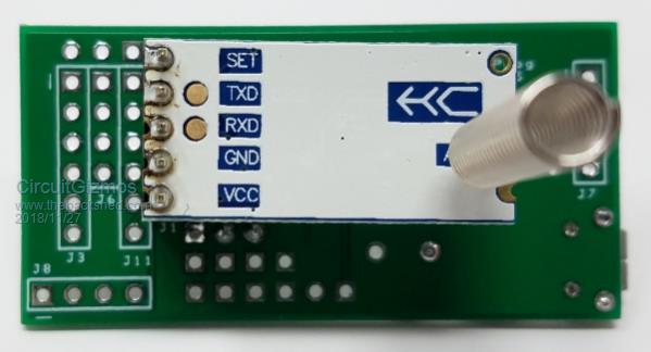 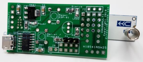 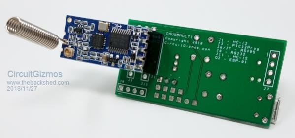 Micromites and Maximites! - Beginning Maximite |
||||
| Grogster Admin Group Joined: 31/12/2012 Location: New ZealandPosts: 9066 |
I'm no RF expert, but I can't see any reason why that should not work. They are sold with those little helicals and that is how you are probably supposed to mount them. The range might not be as good as it COULD be with the perfect antenna arrangement, but if you obtain the distance you want with any given antenna setup, then it's all good.  Smoke makes things work. When the smoke gets out, it stops! |
||||
| RossW Guru Joined: 25/02/2006 Location: AustraliaPosts: 495 |
From the boards point of view, I don't believe it would make much difference which side the antenna came out - I have some small boards where I have it coming out the end, along the axis of the board (which is mounted vertically) Most of my applications have the boards inside an enclosure, or metal case, so I use a "real antenna" anyway and use an IPEX->SMA tail. |
||||
Timbergetter Regular Member Joined: 08/10/2018 Location: AustraliaPosts: 55 |
It would be interesting to see if 3 or 4 similar spirals arranged radially around the base as a ground plane would improve performance. On the other hand if you had the space to fit such a thing you would probably be better off with a regular whip. |
||||
| CaptainBoing Guru Joined: 07/09/2016 Location: United KingdomPosts: 1985 |
I have dozens of genuine HC-12s with the antenna mounted along the back (space problems). Here is another example in my super-simple USB-433MHz adapter. I know this is far from ideal but they all work just fine so for me it is't a problem. 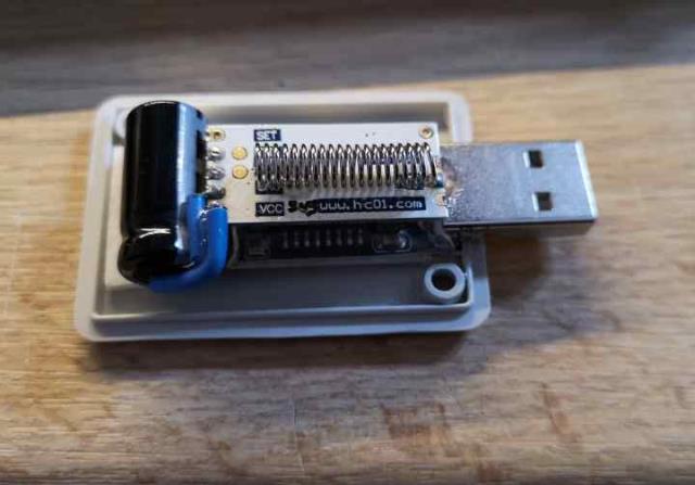 |
||||
| Grogster Admin Group Joined: 31/12/2012 Location: New ZealandPosts: 9066 |
I see you have a big juicy electro on the power supply pins. Did you fit that, or did the USB dongle come like that? Smoke makes things work. When the smoke gets out, it stops! |
||||
| RossW Guru Joined: 25/02/2006 Location: AustraliaPosts: 495 |
I noticed that, and thought "Someone actually read the documentation!" (It says: "It is recommended that a reservoir capacitor be provided across the power supply of at least 22uF, preferably 1000uF." which seems waaaay overkill to me. A lower value cap of decent ESR should be quite adequate unless you've got a real soggy power supply!) |
||||
| Grogster Admin Group Joined: 31/12/2012 Location: New ZealandPosts: 9066 |
I often provide a 100uF 6v3 cap on the HC12's 5v supply, but I have run them with no cap at all, and I have never had any issues....  I always use a 100uF/100n arrangement close to the HC12 power pins if I can possible get it in there - usually I can. I wonder if there is a typo in the manual - perhaps they meant 22uF - 100uF? Smoke makes things work. When the smoke gets out, it stops! |
||||
| RossW Guru Joined: 25/02/2006 Location: AustraliaPosts: 495 |
A typo? In a Chinese manual? Surely you jest! :) |
||||
| Grogster Admin Group Joined: 31/12/2012 Location: New ZealandPosts: 9066 |
LOL!  Smoke makes things work. When the smoke gets out, it stops! |
||||
| CaptainBoing Guru Joined: 07/09/2016 Location: United KingdomPosts: 1985 |
@Grogster, @RossW The stack here is very simply a CH340G underneath with the HC-12 mounted on top with hot glue (I know, don't hate me!). As you noted, the PDF warns of big current req's in high power mode so I went for the biggest can I could get in the tiny case. There is also a 100nF in there too but not visible. Four components to get a PC talking on the 433MHz network and about �5... most expensive part was the case! |
||||
| RossW Guru Joined: 25/02/2006 Location: AustraliaPosts: 495 |
And just a note from the fun police (as has been mentioned earlier in this thread, but in a slightly different context) - it you are planning to operate, on-air, in the field, in high-power mode, just make sure you do the appropriate checks for power limits within your chosen band in your geographic and political environment. Although the genuine HC12 modules seem quite capable of transmitting at +20dBm, that isn't legal under all conditions and in all countries. (Side note: the regulations are typically EIRP, so with bad enough antennas and coax, you might not actually be operating illegally, even with the full 100mW out the module) |
||||
| CaptainBoing Guru Joined: 07/09/2016 Location: United KingdomPosts: 1985 |
... and your point is well taken. I have hc-12 networks installed at four snooker clubs in the southern half of the UK with a MM+HC-12 in a replacement ceiling rose to control the lights over the tables - it's a simple conversion, then all the existing light switches are left on at the wall. Largest club has 17 tables and no extra wiring! Each site was subject to a radio survey with scanners and one of the transmitters to ensure the channels chosen were quiet and we didn't annoy the neighbours (nothing in 1-2 years). One of these is using full power as the network is across two floors. I wrote a wireless protocol to run the whole network with discovery etc. the software for which is published here |
||||
| BobC Newbie Joined: 10/06/2017 Location: United StatesPosts: 9 |
I'd like to measure the power out of the HC-12's I have. I have a HP8560E SA. I've tried to set the SA up but not doing well. Anyone have the setup for an 8560E? I'm seeing the TX signal but can't measure the PO. Got a 10 dB atten on the input and direct connect to the HC-12 via an IPEX/SMA. Not an RF engineer.... Bob WA1EDJ |
||||
| RossW Guru Joined: 25/02/2006 Location: AustraliaPosts: 495 |
Hi Bob, what are you getting/seeing? A couple of things that are perhaps easy to overlook. 1. The board won't transmit until you give it something to send. I set the interface to 1200 baud (fairly slow, so maximum airtime), and wrote a 1-liner that just spat out a 50 or 60 byte string constantly. 2. The RF is still only a fairly brief burst on the air, and if your SA is not listening to the exact frequency at the time, you'll miss it. Set the SA to display peaks (peak hold, maximum hold, whatever) and leave it run for a while until you accumulate enough data to display. If you're using the clones, and if you're unlucky - the signal could be as low as -30dBm, so if you can't see anything initially, you might have to go looking for it. Have you got the SA set so you can see the noise floor? If not, wind the ref level down until you can. Have you checked your centre frequency, and the channel the HC12 is set to? Only channel 1 is on 433.400MHz (nominally). |
||||
