
|
|
Forum Index : Electronics : Various aspects of home brew inverters
| Author | Message | ||||
| Tinker Guru Joined: 07/11/2007 Location: AustraliaPosts: 1904 |
|
||||
| Solar Mike Guru Joined: 08/02/2015 Location: New ZealandPosts: 1129 |
Actually RS Components have them less expensive than on AliExpress RS PCB Transformer , many different voltages and more importantly they have 230 or 240 VAC primaries; the Aliexpress ones usually have 220vac and more likely to burn out. |
||||
| wiseguy Guru Joined: 21/06/2018 Location: AustraliaPosts: 1017 |
|
||||
| poida Guru Joined: 02/02/2017 Location: AustraliaPosts: 1392 |
whoops, sorry Wiseguy. I find it a bit of a struggle to keep up with all the comments sometimes. I suspect I am getting a bit burned out over this thing. Maybe I just shut up and code to request from now on. That would be the easy way out. TO all here: I am beginning to see the discussion on the VFB source to start to look like something I saw in committee meetings in the past. That is, one voice can speak without any challenge, as long as the subject is something arcane or very specialised, to the extent that all the listeners know they have no idea on what is being spoken. But when the discussion moves on to something we all know about, then it's on. It's On And It's Going To Be A Long Night.... If we can just chose a VFB source which will not blow up the opamp's input and presents approx 3V DC to the nano ADC input I'd be grateful to all. Personally, if you ask me what I worry about it's a couple of things. The mains sync is still a bit glitchy when fed real world sync sources. I have no idea what is happening but I will get to the bottom of it - when? No idea but I love a puzzle. Some people here may chose to build test inverters or even build a proper working one for the house. I hope it does not explode. That is not what I want. wronger than a phone book full of wrong phone numbers |
||||
| wiseguy Guru Joined: 21/06/2018 Location: AustraliaPosts: 1017 |
Poida, I agree it has been a long journey with a lot of contributions - I have tried to minimise my input as I did not want it to be a case of too many cooks. Thank you for your & Tinyt's ongoing efforts to date, can I try to offer some clarity/directon for the feedback voltage. I propose a voltage divider to the input of the filter opamp with the intention that a max 260V into whatever transformer drives the divider & has a divider output of around 4V to the filter input. The upper divider resistor is simply a "select" value to suit the voltage sense transformer used. The unfiltered divider tap voltage could also be sent to the nano2 for output voltage display. Keep the active filter. If anyone disagrees or doesnt want it then just leave off the opamp & join pins 3 & 7, voila no filter. The output of the filter could contain the trimpot used to determine the output voltage value, suggest range of 190 - 250 or similar. The high end of the trimpot could be used as a filtered feed of the actual inverter output voltage" to nano2. Is the majority of your time and efforts best spent on getting the code right without adding extra hardware stuff to your considerable work load? With regard to technical design, the main contributors (apart from you) are Solar Mike Tinyt & myself. Why not assign us to "discuss" & brainstorm to provide an appropriate solution (or two) to whatever design is needed and you can help with a final decision especially if it affects your coding - or you just hate the solution ? If at first you dont succeed, I suggest you avoid sky diving.... Cheers Mike |
||||
| tinyt Guru Joined: 12/11/2017 Location: United StatesPosts: 431 |
OK guys, how about this. 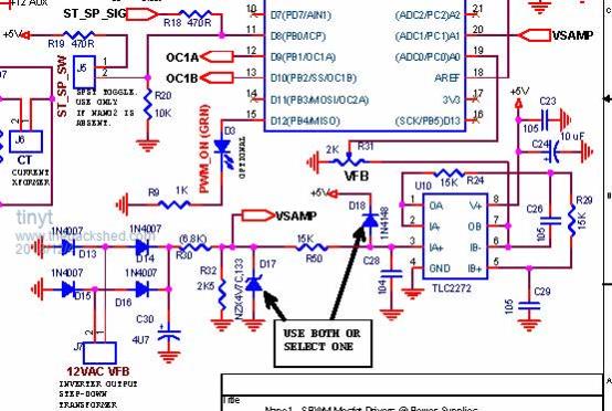 As in rev A, VSAMP is also connected to nano2 pin19 with a 105 cap to gnd. VSAMP connection to nano1 is there as an option to code for or not. Please review and comment. Thanks. |
||||
| Solar Mike Guru Joined: 08/02/2015 Location: New ZealandPosts: 1129 |
Hi TinyT, the filter was suggested to remove the HF noise and voltage transients from the supply, in order for the CPU's ADC to have a clean low impedance input to measure; placing the 2K pot on the low impedance Op amp output is not a good idea, it should remain on the input as originally planned as its adjustment to the correct level for the op amps will also attenuate any noise prior to filtering. If Nano2 now requires an independent voltage source, then ideally it too should have its own filter to get a clean voltage signal. I know for some this is making the design more complex and why do we require the filter at all. The noise around these inverters is extremely high, its a tall ask for the CPU ADC to make an accurate measurement in these conditions. When we have an ADC measurement requirement, ideally there would be some sort of low output impedance filter at or very close to the CPU's pin. I find it easier to have the filter on its own postage stamp pcb with 4 rt angle pins and solder them to the main pcb as required, the filter capacitors should be film type and they do take up more room. Cheers Mike |
||||
| poida Guru Joined: 02/02/2017 Location: AustraliaPosts: 1392 |
D18: IN4148 specs Vf = 0.6V at near zero current, rising to 1V at 10mA Having this clamping input to 5V + diode drop still permits the TLC2272 to receive inputs exceeding supply voltage. T.I. specs have on page 5 the max input pin voltage limit = supply voltage. I suppose this tight upper limit is due to the rail to rail design? When I build my board, I will only use the zener. this 4.8V NZD series probably wronger than a phone book full of wrong phone numbers |
||||
| Solar Mike Guru Joined: 08/02/2015 Location: New ZealandPosts: 1129 |
Poida is correct to be cautious, and depending on what transformer, Resistive dividers etc being used then an op amp with same pin out but higher voltage capability on its inputs could be substituted, LT1638, I have used both in these filters with same measured results. The Linear LT1638 is a rail to rail non-cmos micropower, with higher voltage and output, perhaps better suited if builders mess up the voltage dividers, or use a higher voltage transformer. Cheers Mike |
||||
| tinyt Guru Joined: 12/11/2017 Location: United StatesPosts: 431 |
Here is the revised nano1 schematic with LT1638 opamp filters used for VFB and VSAMP. 2018-12-04_131058_SCHEMATIC1___Nano1.pdf Please review and comment. Thanks. |
||||
| Solar Mike Guru Joined: 08/02/2015 Location: New ZealandPosts: 1129 |
Looks good TinyT. These tiny PCB mounted transformers with dual 6v windings from RS are quite cheap and high quality, I have just ordered a couple for another project. Note the unloaded output voltage is somewhat higher, so those using 12 vac versions coupled with the x 1.414 for peak DC means the final DC voltage could be rather high, be wary and adjust the divider accordingly prior to inserting the op amps. RS 6+6 vac Pcb Transformer Cheers Mike |
||||
| poida Guru Joined: 02/02/2017 Location: AustraliaPosts: 1392 |
Solar Mike and Tinyt: Correct me if I am on the wrong track, but the change to LT1638 opamps means we no longer need to care if inputs are a bit over the chip's V+ supply. The specs seem to read as up to 44V from V- will not be a problem. If so, then that is why protection zeners/diodes have been omitted from the latest schematic. I really like the idea of having approx (44-5)V headroom for inputs into the active filters. Bullet proof? As I said earlier, I worry about other people's inverter blowups. Mine? I have no problem. I have lost count how many times the prototype inverter has ended up in some bad state of affairs with the power supply current limiting and some ugly twisted waveform on the DSO. I can deal with this. But to hear of other's builds, costing them real money and time exploding is not something I can tolerate. wronger than a phone book full of wrong phone numbers |
||||
| Solar Mike Guru Joined: 08/02/2015 Location: New ZealandPosts: 1129 |
You are on the right track Poida, the LT1638 has a much higher input capability albeit at a higher cost for the PDip versions. Actually it would still be a good idea to keep the silicon clamping diode in place between the input pin and +5v, I don't know what sort of transformer voltage people are going to use, and if they mistakenly use the wrong resistors in the divider then keeping the diode may save the op amps. How fast does the Nano respond to voltage changes on the AC, seems we are at the mercy of the RC time constant of the bridge rectifier and capacitance + loads. With the Nano couldn't you just measure the P/P AC off the transformer directly to give a more accurate and faster measurement?. Cheers Mike |
||||
| wiseguy Guru Joined: 21/06/2018 Location: AustraliaPosts: 1017 |
Solar Mike - is it a good plan to have a voltage feedback trimpot with no low side resistor to set a range. If someone powers up with or adjusts the trimpot to zero, effectively with no feedback wont it just drive the output to maximum ? I also dont follow why there are 2 filtered voltage inputs on nano1 pins 19 & 20? Ive taken myself out of further design suggestions, I'll just comment on what the committee has decided. If at first you dont succeed, I suggest you avoid sky diving.... Cheers Mike |
||||
| tinyt Guru Joined: 12/11/2017 Location: United StatesPosts: 431 |
I think the pioneers used the isolated transformer approach for VFB. Just following what others have successfully built. But if the EG8010 fig 8.1c datasheet is followed, the hardware will be simpler (or maybe not, datasheet fig 8.1c shows dual tracking trimpot and two identical chokes). And if EG8010 fig 6-6 datasheet is followed, then there could be lethal 220vac on the control board. Right now I am just doing 'paper drawings' and incorporating what is being discussed. Here is the revised nano1 schematic for review/comments.2018-12-05_021315_SCHEMATIC1___Nano12.pdf 1. Restored resistor at the bottom of the VFB trimpot. 2. Restored diodes to +5V at the input of the opamps. (PN = TBD) 3. Restored zener diode between the top terminal of the VFB trimpot and gnd. (PN = TBD) 4. Added note for VSAMP connection to pin 20 of nano1 (this is for me to learn coding but I can remove the connection if it creates confusion) |
||||
| poida Guru Joined: 02/02/2017 Location: AustraliaPosts: 1392 |
The closed loop control works in a similar way to the EG8010. Both my code and the EG8010 use a DC Vfb signal. Whether the DC Vfb signal carries a bit of AC on top or not is not an issue. The 80180 feedback control details (i.e. if it's PID or some other scheme) I will never know. But I do know, and have proven that the EG8010 samples Vfb once per 50Hz cycle, and the sample time is very narrow, about 10uSec. The timing of this narrow sample event relative to the 50Hz phase angle is constant and if I recall correctly, is at the top of one 1/2 cycle. Nano1 control loop works as follows: at a rate of 4000Hz, sample Vfb and digitally low pass filter this to a much more noise immune value. At the start of either 1/2 cycles of the 50Hz output, apply PID control to PWM duty cycle %, depending on a constant set point and the filtered Vfb. Since the PID control occurs at a constant phase angle with respect to the output AC, we can get away with varying amounts of LP filtering on Vfb permitting AC to ride on top of the DC signal. I expect I will need to retune PID values once the control board is built. It will undoubtedly have a LP filter Fc and passband characteristics completely differing to my prototype, on which I have developed the code. My Vfb "filtering" is the result of a 9V AC unregulated plug pack, (diode bridge, then 10uF or so capacitor), into a 1000R multi turn trimpot. This then travels past the MOSFET bridge picking up plenty of HF rubbish, and into the 328p uC ADC channel. I wanted a badly performing, noisy Vfb signal. Why? To force me to implement effective filtering on input into the control loop. Poor filtering will immediately become apparent and force a better solution. This project will likely have much cleaner Vfb signals. I will probably not need as much digital filtering and we might be able to have a little faster responding PID control. Only after testing will I know. Bad things happen when Vfb is LP filtered so much that less than 1Hz passes through the filter attenuated to significant degrees. The output voltage ramps up and down at sub Hz frequencies. Maybe if I could make a note for all here. I would rather I build a test rig using the finalised Vfb circuit, and explore the closed loop control performance BEFORE anyone uses the controller with their expensive power boards. I better get some LT opamps ASAP from RS, I hope they have stock. How fast it responds? Fast enough. I use PID to provide accurate tracking of the setpoint mainly, not fast response to load transients. wronger than a phone book full of wrong phone numbers |
||||
| poida Guru Joined: 02/02/2017 Location: AustraliaPosts: 1392 |
I would want low side resistors too, the inverter will go to 100% PWM if the trimpot is set incorrectly. I suspect it would be best if before first use of the control board, the builder applies 240V (or 120V, Tinyt) to the 12V transformer and adjusts output at the trim pot wiper to be about 2.7V This 2.7V corresponds to the value (as seen in nano1 code) of ac_setpoint = 0.56; As for why 2 filtered voltage inputs, I am OK with this. It allows nano1 to recognise when Vfb is improperly set or Vfb filter/opamp is bad, IF I code such a function. wronger than a phone book full of wrong phone numbers |
||||
| tinyt Guru Joined: 12/11/2017 Location: United StatesPosts: 431 |
Here is complete schematic revised to rev B. 2018-12-05_133740_nanoverter_Rev_B.pdf Please review/comment/etc. If there are no more corrections/changes, I will work on the gerbers. Thanks |
||||
| poida Guru Joined: 02/02/2017 Location: AustraliaPosts: 1392 |
Thanks again, Tinyt. wronger than a phone book full of wrong phone numbers |
||||
| wiseguy Guru Joined: 21/06/2018 Location: AustraliaPosts: 1017 |
I think R23 should ideally be located on the other side of the diode bridge as per the Oztules design, the circuit and values should just work as before. Maybe allow 2 pads for the input side of the bridge for evaluation. As it is now the voltage applied to the sense circuit will be at least ~ 1.3V less than the original and any Vf temperature effects of the bridge are not compensated for automatically. During low currents the first 1.2V of current signal generated by the current transformer will be lost & only higher currents will be able to be measured. Other than that it looks good to go. If at first you dont succeed, I suggest you avoid sky diving.... Cheers Mike |
||||
