
|
|
Forum Index : Electronics : Various aspects of home brew inverters
| Author | Message | ||||
| johnmc Senior Member Joined: 21/01/2011 Location: AustraliaPosts: 282 |
Poida That sounds good news for the nanoinverter, as your tests show, it makes no difference at what voltage level the dc bulk caps are at, when the inverter is switched on. Am I correct, that when the nano inverter is switched on, there will always be a soft start. MOST impressed . cheers john johnmc |
||||
| poida Guru Joined: 02/02/2017 Location: AustraliaPosts: 1392 |
John, nano2 on boot initialises to a state of inverter OFF and a re-initialise of the firmware in both microcontrollers. Inverter OFF will send a signal to nano1 to not run the inverter. When I examine outputs of nano1 and IR21844, I see no gate drive voltages other than ground level after DC supply is first switched in. So, on boot (when power is applied) things are stable. Always, it is up to the user to start the inverter, and a start will be a soft start. When we stop the inverter using the run/stop button, we see a soft stop. DC over current, DC under voltage and others will trigger a soft stop. In the case of DC under voltage stop, nanoverter will restart automatically, and in a soft start manner, once DC voltage exceeds the programmed restart voltage. Only the SCR over current circuit causes an abrupt inverter stop. (within a few ms) While playing with my inverter on the bench, when DC supply is removed, we get a sort of soft stop, caused by the drop in DC voltage which is sent out the full bridge. Both nano1 and nano2 continue to run.. There is no longer enough voltage in the bulk caps to maintain the desired AC output voltage. Then they suspend execution of firmware when DC drops below about 8V. By that time there is little or no current driven into the transformer primary. And when DC supply is regained, the system is in the stop state, initialised as above. It is best to define a reasonable DC under voltage cutoff limit, and enable this to stop the inverter. This will soft stop the inverter as DC supply drops. If the user does not want it to restart when DC volts rises enough, then we have a problem. It is assumed by me that we want the inverter to always restart when DC volts are high enough if it stopped due to DC UV. I might need to add another user control to nano2 code: Disable automatic restart (Yes,No) The code assumes the setting is Yes right now. wronger than a phone book full of wrong phone numbers |
||||
| johnmc Senior Member Joined: 21/01/2011 Location: AustraliaPosts: 282 |
Poida, Thanks for the explanation, I intend to use the Inverter mobile, with a 24v supply. (my prefered supply of 48v alternator for motor vehicles, requires very deep pockets) The option of automatic restart may be useful but not important. Thanks again for the efforts of you and the back shed team. cheers john johnmc |
||||
| ltopower Regular Member Joined: 08/03/2019 Location: United KingdomPosts: 64 |
Been doing some more testing on the inverter using two E70 gapped chokes on the primary and noticed a few things.... thought this was themost interesting... 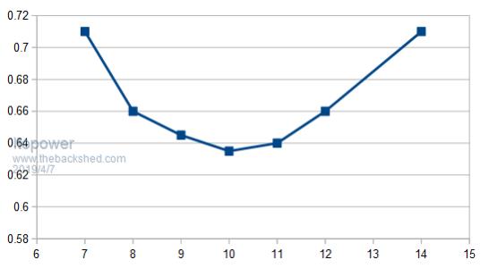 The idle current has a "sweet spot" for minimal current draw depending on the inductance (the bottom axis is turns). This setup the chokes had a saturation around 43A per choke, two in parallel, so about 4.1kW at nominal input voltage. While testing and trying to measure overall efficiency there appeared to be a small change in overall efficiency around 4.1kW. This may have been by chance or not.. So far I must have tried and wound well over 50 choke variations and many screen shots of the scope output. But, even with all that I'm still struggling to actually see the true "consistent" effect of the choke behaviour.  This is the impact on idle current draw compared to the battery input voltage.... 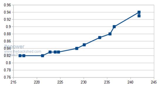 This is the impact on idle current with various output voltage settings (no change to choke arrangement). Separate set of data also shows specific knee point where I think the "ideal" choke inductance occurs. For all the testing so far I'm becoming more convinced that there is a specific inductance required per inverter. Above that point losses increase. Below that point losses increase. What I'm still not clear on is does the minimal no load idle losses really actually represent the ideal inductance to be used under load..... |
||||
| ltopower Regular Member Joined: 08/03/2019 Location: United KingdomPosts: 64 |
Another interesting thing I noticed while testing chokes was the impact of partially winding a toroidal transformer, as per the way victron inverters are wound. There is a research paper, which goes on to correlate the unwound segment with leakage (psudo air gap inductor inline) and a softer inductance. What I found with some other testing is that by grouping all the windings in a smaller portion of the choke the resulting inductance measurement was increased.... while increasing leakage (simulated air gap). This combination could be an ideal way to get the gapped effect of a choke while getting a higher inductance value out of a toroidal unit. This was with the large T400 that arrived, so wondering with a toroidal unit, for a choke if we are after a gapped effect, why evenly space all the windings.... ? For my last/latest setup and testing I am now onto choke test number 100+ and have two E70 cores gapped together and two of those in parallel (4 E70 cores in total), which should give a core saturation current of 70A per choke, so hopefully 140A in parallel (6.7kW). Will be testing this soon... Effects (seen on scope) on switching time also seems to vary as if there is some other secondary pulse to pulse resonance occuring which increases and reduces the delay effect of dv/dt ? Maybe just my scope skills... |
||||
Ralph2k6 Senior Member Joined: 24/09/2017 Location: AustraliaPosts: 129 |
Very useful information Karl, pls keep up the good work. I'm looking to salvage some 400 watt discharge lighting ballasts for consideration (very back yard I know). Ralph |
||||
| poida Guru Joined: 02/02/2017 Location: AustraliaPosts: 1392 |
ltopower: When my 3000VA Victron Multiplus inverter/charger died, after 25 months (I enjoyed a 24month warranty only), it p..sed me off to an extent I chose to build my own inverters from now on. The educational journey took me to that paper you referenced above. Very interesting read. I tore down the Victron completely since it was unrepairable for reasonable cost in my view. The 3000VA Victron has two small toriods, not one large one. This allows very low idle power losses, since the unit drives one toriod only at (say) 500W and lower outputs, switching both in for larger loads. I saw no inductor in the primary winding circuit. I was puzzled and so the search led to the above paper. On the bench, I am right now testing the Madness power board with my nanoverter control, into one of the Victron's toriods, with a 50uH ferrite choke and 10uF across the 240V output. This delivers excellent looking AC output, almost zero sound and idle current is about 0.35A at 60V. The primary winding is very "one sided", all the turns are bunched to one part of the toriod, approx 1/2 the circumference. This is the opposite of our standard practice here on the forum, where we aim to have all the turns as evenly spaced as possible. I think this effect only applies to the coupling of the two windings of the toroid. In the case of an inductor or choke, there is one winding only. Having all the windings grouped in the same region with a toriod core won't make much difference, I think it might reduce the inductance, not what you want. some measurements of the Victron toriod (at 100Hz, BK 879B LCR meter): Toriod made by Keen Ocean, TTO-13987-01 27V winding, 240V winding. 2 of these are used in a 3000VA Victron. Not a big transformer, 0.43V/turn at 230V on the output. In size comparison, I would estimate it to be 3/5 the size of the 1500VA Aerosharp toriods, which have 0.715V/turn at 230V on the output. Secondary (240V) shorted, the 48V primary is 193uH Primary (48V) shorted, the secondary is 12.1mH I wound an extra 24V primary on the outside, and evenly distributed the turns. When this is shorted, the 48V primary is now 3.8mH When I short the secondary 240V winding, the hand wound 24V winding, evenly spaced, now shows 11uH. This is a more typical leakage inductance and this small amount is why we need the primary chokes. We can see the effect of even and bunched primary windings when they are shorted, on the leakage inductance. The 1500VA Areosharp, with 18 turn primary (18 x 0.715V = 12.8V AC RMS) evenly spaced has a leakage inductance of 7uH when the secondary is shorted. Compare that 7uH with the 193uH of the Victron toriod. I have tried to run test inverters with the Victron toroid and without any choke. The results are not great, and I prefer to run it with a good 50uH E core ferrite even if it uses a few more watts. wronger than a phone book full of wrong phone numbers |
||||
| ltopower Regular Member Joined: 08/03/2019 Location: United KingdomPosts: 64 |
Interesting. Tried grouping the windings on a T400 ferrite toroid and it increased the inductance compared to evenly spacing the windings. More they were bunched up the higher the inductance. I'm still trying to properly understand inductors and how they fully behave with inverters and switching, while avoiding going down a rabbit hole of more and more complex maths...... Is the switch off transition where all the problems end up (hence the lowering of gate resistors). Too large (physical/materially) a choke and the stored energy causes a large overshoot like when the FET assasin  was having repeat failures ? The overshoot (excess joules in the core) kills the FET's if the excess energy has nowhere to go in the di/dt timeframe. This is where I'm wondering the choke needs to be balanced on uH AND cross sectional area/material for a mj per A over the switch off transition ? was having repeat failures ? The overshoot (excess joules in the core) kills the FET's if the excess energy has nowhere to go in the di/dt timeframe. This is where I'm wondering the choke needs to be balanced on uH AND cross sectional area/material for a mj per A over the switch off transition ?Interesting you tried the victron out with 193uH leakage, given the boards designed and used here tend to need between 35 and 70uH was the 193uH too large a leakage, higher idle losses ? Would be really great if the home wound toroids could be done with the right level of leakage to avoid the choke, although not sure on the overall idle loss impact.. Need to wait for some sun to charge the battery bank back up so I can test higher loading out again with the double double choke arrangement.. been thick cloud and rain here for 2 days. |
||||
| noneyabussiness Guru Joined: 31/07/2017 Location: AustraliaPosts: 506 |
Poida, curious question, would it be possible to implement a scaled current limit? ? Why i ask is people like myself who intend to use your wonderful code / design to parallel 2 inverters to increase capacity of my system. Would be useful to limit 1 inverter to its allowed maximum,but still pull its weight ?? I understand the " master " will have to take on the start up surges etc. Im in the process of building the board you sent me ( waiting on parts etc. ) so if its a mute point ten i understand. I know building and using it , is very important as it probably will naturally limit... I think it works !! |
||||
| poida Guru Joined: 02/02/2017 Location: AustraliaPosts: 1392 |
Noneya, I'm not confident I understand "scaled current limit" Assuming it is as described below... (in a 2 inverter system, with synchronised outputs) Maybe you mean for one inverter to provide any output current up to a defined limit and no more, letting the other inverter provide power to it's limits. I could add a bit of code to nano1, looking at another analog input, maybe DC suppy current. The code would reduce output voltage a bit, when the analog input rises above a setpoint. That might not work as expected. These inverters we build are expected to draw current from the DC supply, and provide an AC voltage source on the output. i.e. one way power flow from battery to AC load. They can just as easily draw current from an AC source, attached to the toriod's 240V output, and send that backwards into the DC supply, and then, battery. We might need to look at the DC current direction, as well as magnitude now. Possibly, I could design something that reduces output power to achieve a desired DC current draw when enabled. e.g. - have inverter #1 just run at all times, up to it's set limits. - have inverter #2 run up to a defined DC current limit and no more, backing off PWM duty % as needed to maintain DC supply current at the set limit. It would turn off if DC current flows backwards, into the battery. This might work OK. In slow changing load scenarios, the control loop for #2 current limit might keep up. In fast changing events, it might over shoot or worse. No idea. wronger than a phone book full of wrong phone numbers |
||||
| noneyabussiness Guru Joined: 31/07/2017 Location: AustraliaPosts: 506 |
Thank you, nail on the head. .. Sounds too much, because like many i have OGI's on the output too... so there will be constant bi-directional current. .. i wouldn't wanna even try to code that. It was just a thought. I was thinking hard current limiting via some beefy inductors on the output of the slave inverter, not too much to choke it, but enough induced resistance to do its thing... What are your thoughts? I think it works !! |
||||
| hugocamaras Newbie Joined: 12/04/2019 Location: BrazilPosts: 24 |
Hi Madness, I would like to build your power board design. Can you publish the pdf of the latest version of your power board? PCB_Top, PCB_Bottom, and PCB_Silk? Thank you, Hugo. |
||||
| noneyabussiness Guru Joined: 31/07/2017 Location: AustraliaPosts: 506 |
poida, could you please post updated code and schematics here, ive got a few different versions and i just wanted to confirm which is right.. thank you for all your hard work and effort. I think it works !! |
||||
| poida Guru Joined: 02/02/2017 Location: AustraliaPosts: 1392 |
Happy to help. I post latest code, for both nanos, and Tinyt's schematics and PCB files. This is what I am running now, on the test bench. There is still behavior of the low voltage cut-out/restart that I am not quite satisfied with. It concerns the situation where LV cutout was triggered and power is removed for a short period. I want LV restart to be disabled on this situation, instead the inverter starts by itself upon application of power. LV cut-out/restart works fine if DC power remains connected. It's the marginal condition where DC power gets disconnected for a short period, then reconnected... I will get something better in the near future. The changes will occur in nano2 code only. 2019-04-14_172241_pcb_images.zip 2019-04-14_172312_2018-12-11_061353_Nanoverter_B_Gerbers_Others.zip 2019-04-14_172332_nano2_4.ino.zip 2019-04-14_172357_nano_1_v7_no_bessel.ino.zip wronger than a phone book full of wrong phone numbers |
||||
| noneyabussiness Guru Joined: 31/07/2017 Location: AustraliaPosts: 506 |
Thank you as always I think it works !! |
||||
| poida Guru Joined: 02/02/2017 Location: AustraliaPosts: 1392 |
Part 30: External influences beyond any reasonable hope of control And so, it has come to pass... 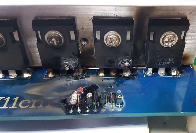 This is an inverter driven by an 8010, and the 50Hz 1/2 bridge blew up, taking the gate drive diodes, resistors, all 6 MOSFETS, and the EGS002, and the 2 TVS protection diodes. Things were going so well: that's what we always think. Here is the data from my monitoring system. 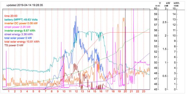 The failure occurred where the black vertical line is located, almost exactly 8pm or 20:00hrs It shows the DC power drawn by the inverter, in Orange. See the two large peaks just before failure, and the rest of the day was low, maybe only 250 to 500W. What happened? My wife had done some rearranging of the power leads and stuff in the spare room. This room is where she runs her academic editing business. For heating we have a 3 bar radiator. I have wired in most rooms, including this one, duplicate power outlets. One is street power, one is solar power sourced. (getting warmer?.... bad pun, sorry) She had cleaned up and made more rational, all the 1/2 billion cables we have, for the home office in that room, and placed everything onto the solar power outlets. Including the radiator. In the past my blowups had never dealt such damage to the gate resistor/diode network. Those were the result of bad voltages finding their way back to the gate drive IC inputs. This time I think this is what we get when we run things too hard and the MOSFETS get too hot. I had the inverter board running again the next morning and I have relocated the radiator to use street power. And I asked my wife to consult with me prior to changing the supply of power for any appliances in the house from now on. wronger than a phone book full of wrong phone numbers |
||||
| Tinker Guru Joined: 07/11/2007 Location: AustraliaPosts: 1904 |
LV on my inverters trips the over current FET. Inverter has to be manually reset to soft start again. Very simple and 100% effective. The reset has to be pressed also after initial capacitor charging (as in connecting to the battery) since the slowly rising DC powers the 5&12V control before the trip threshold voltage is exceeded. Threshold is selected by choosing 3 zener diodes. Klaus |
||||
| poida Guru Joined: 02/02/2017 Location: AustraliaPosts: 1392 |
this will work. No risk of malfunction. I use a LV cut-off and auto restart function at home, nearly daily during the darker months of the year. It lets me use whatever I managed to harvest from the day's solar power for as long as the battery can keep above a certain voltage. Then the house switches over to street power. The sun comes up next morning, battery gets enough and the inverter switches on again. I do not need to manually intervene. We just let it do this, for weeks on end. So a manual reset is not going to be useful for me. I suspect I need to monitor DC voltage and if the voltage drops below some value, a few volts less than LV cutoff, then reset the LV cutoff to require a manual restart. If DC voltage only drops below LV cutoff value and then rises a bit, to remain there until the next morning when charging starts, then leave the auto restart alone, permitting it to restart when voltage exceeds the restart voltage. Probably look at this code in nano2 next week. wronger than a phone book full of wrong phone numbers |
||||
| Tinker Guru Joined: 07/11/2007 Location: AustraliaPosts: 1904 |
I see, you are still using street power as well - I do not and did not realise you do. Regarding your excellent blow up picture above, you can see the mosfet got hottest just above the source leg. That is exactly where inside the black housing the two tiny wires from the leg to the substrate are located. Yours was a slow heating effect, a fast one blows the housing apart just there. Interesting to see you recorded the trace of the event. At least now you have a good excuse to build a much more robust (against overloads) inverter from scratch   . . Klaus |
||||
| ltopower Regular Member Joined: 08/03/2019 Location: United KingdomPosts: 64 |
Brilliant post, shame about the damage. I'm guessing it's the same board you lnked to a post in another thread (BenandAmber). Interesting overheatin, the load appeared to be around 2.5kW with FET per leg, which seems low ? Colling fan issue ? Choke saturation ? Think I might be applying more solder to the legs on my board to help with the heat dissipation a little. I left it after the last post, but will re-visit and sodler them. Is it possible to add a small heatsink / bar to the front of the FET as well ? Drill through a small aluminium bar and bolt it to the front of the FET packages (using the through bolt) ? Downside might be blowout failures might cause a bit more damage ? The other option I was looking at was dipping the FET board in oil and removing the majority of the heatsink, although I wondered how FET failures would behave under oil, throwing oil. |
||||
