
|
|
Forum Index : Electronics : Various aspects of home brew inverters
| Author | Message | ||||
| noneyabussiness Guru Joined: 31/07/2017 Location: AustraliaPosts: 506 |
Im not sure on the explosive effect on the oil, but i have a oil cooled version of the same board poida is using, with eg8010 at moment, fully immersed with transformer. At current state ive pulled 5kw through it until my battery has winged... it still needs a lot of tweeking. Ill do i post soon, wanna use the nanoverter instead and make sure its robust. I couldn't get a reasonably priced transformer up here and most cheaper ones are killed by postage. I did manage to get one 2kw aerosharp that i salvaged the core from for it. I think it works !! |
||||
mackoffgrid Guru Joined: 13/03/2017 Location: AustraliaPosts: 460 |
Noneyabusiness: I definitely want to see more of that. What type of oil? How'd you go with capacitors? Did you use heatsinks? |
||||
| noneyabussiness Guru Joined: 31/07/2017 Location: AustraliaPosts: 506 |
oil type This the oil i went with (iso 68), now i know before some wiseguy has a crack, yes its not technically " transformer oil ".. but no leakage that ive been able to detect. Temp range more than fine... and water ingress is minimal The board is stock except for the usual mods to disable current limiting etc. And caps have been fine so far... have a few kwhs under its belt, but i want to do further testing before saying its ok... but so far so good... I think it works !! |
||||
renewableMark Guru Joined: 09/12/2017 Location: AustraliaPosts: 1678 |
Never seen power and control boards in oil, that's a new one to me. Cheers Caveman Mark Off grid eastern Melb |
||||
| Tinker Guru Joined: 07/11/2007 Location: AustraliaPosts: 1904 |
Well, if one can't find a big enough heat sink or transformer than that's one way to keep 'em cool. But the oil needs to be cooled too.... And it gets messy if any repair has to be made. Next you'll see somebody using those heat transfer tubes as used on CPU chips. For myself, I prefer the big aerosharp heat sinks  . .Klaus |
||||
| Warpspeed Guru Joined: 09/08/2007 Location: AustraliaPosts: 4406 |
I have seen circuit boards immersed in oil (or light jelly) its quite common for equipment that has to work reliably when totally submerged for long periods. Deep underground mining, anything that floats on or under the ocean, and the military love that kind of thing. Its also common in very high voltage equipment, tens or hundreds of thousands of volts, where air tends to corona discharge and flash over. Oil does not do that, it makes a far better insulator than air. Most common application for oil is in large transformers, particularly large high voltage transformers that stand out in the weather for tens of years, where you get both the cooling and insulation advantages. Cheers, �Tony. |
||||
LadyN Guru Joined: 26/01/2019 Location: United StatesPosts: 408 |
The power company runs power to us at the farm at 140kV. Then there are 3 big blue cans on the pole that steps it down to 2x 110V AC. I don't know why they feed 140kV but that's what they do. That's a huge step down factor. Who knows. One of the cans fell to the ground in a storm a few years ago. Had a few gallons of mineral oil in it. There's a very big transformer inside it but most of the space is for the mineral oil. It was many years ago but the windings were weird like plates instead of wires. I can't explain it and I was not very interested (not understood) electronics back then either. I saw this as they were repairing it to put it back on the pole. They took a whole 3 days to fix it. We had no power for one whole day |
||||
| Tinker Guru Joined: 07/11/2007 Location: AustraliaPosts: 1904 |
That must be a very long feed line to your farm to require 140KV, sure it was not 14? Long distance transmission losses reduce with higher voltages and the wires required for a given power are much smaller gauge then. Transformer oil is very special stuff. It used to contain PCF's (carcinogenic), not sure if it still does. One of my jobs as last year apprentice was to test the reconditioned oil for breakdown voltage, I remember the gap between the electrodes was quite small and the voltage hair raising. The thing with the plates inside could have been a capacitor, used for power factor correction. Klaus |
||||
| noneyabussiness Guru Joined: 31/07/2017 Location: AustraliaPosts: 506 |
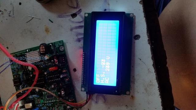 IT LIVES !!! well sort of... poida, as a semi learner on coding... where have i gone wrong with lcd... there is a lot more information to show, it seems to be outside of lcd screen, i have set some of the calibration info... Ive tried to have a play around with positioning of characters but im unfamiliar with the particular library you have used... Thank you in advance I think it works !! |
||||
| ltopower Regular Member Joined: 08/03/2019 Location: United KingdomPosts: 64 |
With the transformer on a pole arrangement, in the south of the UK the transformers tend to be 11kV step down units, while in Scotland the outer aras tend to have 33kV step down where the lines are a bit longer and lower current as a result. The voltage used is not necessarily related to the normal power transmission level, rather the fault current handling capability over a given line distance as this is more critical. The cost of additional step down voltages also has to be factored in, for example a 132kV step down to 33kV and then 33kV to 240V is less cost than an intermediary 33kV to 11kV step down as can happen in the south of the UK with a lot higher load density. The small transformers have fixed fuses that are manually switched, while the larger transformers have auto and remote reset breakers. They typically have something like a 300mS delay between first re-close/reset after a fault, which I think was based on the usual condition of a tree branch touching a line. First flashover would burn away the 'fault' so firest re-close would hold. I spoke with one line engineer, who said that they had a 33kV line down in a field (pole had snapped) and the lines were still separated and laying on the floor. The controll room had tried to 'burn' the fault away, however they just managed to burn 3 large trace lines into the field.... In terms of transformer / cooling oil I did a bit of research on which oil to use and the viscosity is quite critical for low voltage cooling applications as this is what would prevent the oild from degrading due to hot spot heating. Having looked at various mineral oils the end selection (because it was on 2 for 1 bulk discount at the time) is Johnsons Baby Oil.... it is a light mineral oil with a viscosity very close to transformer oil, however at nowhere near the cost or issues over finding a source to buy it from for a few litres at a time. Hydraulic oil is not as good due to the different viscosity, because in the end it is about natural circulation until things need forced circulation for cooling. I had wondered how the capacitors would cope, but figured any internal seep of the oil would not impact the plate separation and therefore no impact on capacitance. The only impact could be the effect of the oil on any glue/fixing internally. Variable resistors a no-no. Relay a no-no. Connector blocks a no-no (only soldered connections) which meant the control board needed to be outside the oil. The thought was to separate off the just the FET and drive electronics, much like the boards you have. Just the FET board with a minimalistic heat sink would then sit in an oil tub. The heatsink/conductor the FET's are connected to would then be just an aluminium bar somethink like 5mm x 40mm so that the cable can be bolted to it and provides a small distance heat transfer. In terms of overall cooling the thought was to use a metal container and then fix heatsinks to the outside of the tub or have a separate water loop to an old recycled radiator (car or house type). Just having a separate thought, some of the heatpipes Tony mentioned, could be dipped into the oil or somethink like this (CPU cooler) : https://www.aliexpress.com/item/Lanshuo-6-Heat-Pipe-3-Wire-Without-Light-Single-Fan-Cpu-Fan-Radiator-Cooler-Heat-Sink/32 975509392.html Or a simple >3m coil of copper say 10mm pipe filled with a refrigerant/propane at a local fridge repair shop... dip the lower section of the pipe in the oil, top part cools. Hmmm.... |
||||
| ltopower Regular Member Joined: 08/03/2019 Location: United KingdomPosts: 64 |
For a shyncornised inverter this is the sort of frequency movement that the control loop needs to be able to deal with - notice the initial swing / change in frequency is rapid over the first second. 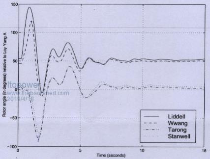 |
||||
| poida Guru Joined: 02/02/2017 Location: AustraliaPosts: 1391 |
You probably have done everything right. The problem might be due to differing LCD controllers. I have coded things using the Arduino LCD library, making calls to lcd.write(), lcd.setCursor(), init, begin etc. This means it should work in most cases. I'll bet there are detail differences in the LCD controllers and the I2C devices we need for this to work. I have some custom functions programmed into nano2. One function lets you see in the serial console what is supposed to appear on the LCD. At the menu, type ^33 and press return The LCD text should be printed underneath the menu. I find that when setting DC current calibration, you don't immediately see the resulting change. I needed to restart the nano2. Sorry if it's a bit of a fiddle. wronger than a phone book full of wrong phone numbers |
||||
| poida Guru Joined: 02/02/2017 Location: AustraliaPosts: 1391 |
Thanks for this info. The nanoverter mains sync code might not be able to follow this. Not to worry, it will detect quite quickly a phase difference exceeding my tight limits and assert "no sync" on it's controls - open the relay and turn off the sync LED. Then it will re-sync and close the relay, light the LED when within error limits. Sync code executes once each positive going edge of the external mains waveform. i.e. at 50Hz. So the fastest response to out of sync condition will be 1/50th second, plus relay contact opening speed. It would likely be something like 2-3/50th second. For any who chose to build a mains tracking inverter using this design, I would hope they also have sensibly chosen contact breakers, to open when AC current limits are exceeded. wronger than a phone book full of wrong phone numbers |
||||
| poida Guru Joined: 02/02/2017 Location: AustraliaPosts: 1391 |
Part 31: Gate voltages observed on a Powerjack LF inverter I have a PJ "6000W" inverter gathering dust here. Since we know it has quite interesting gate drive circuits for low and high side, I wanted to have a look at what is going on. here is the low and high side schematic: 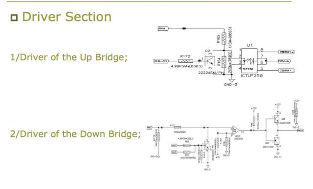 The high side is opto isolated, using a TLP250 The low side is totem pole, using 2SA1213 & 2SC2873 transistors. Testing was done with 52V DC supply, into the same choke/toroid/cap combination Idle current is 0.38A. This ran very quiet too. OK then, let's see the DSO captures. Here is the PJ control and powerboard AC output: 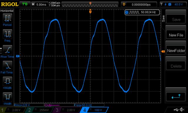 But anyway, Gate to Source voltages... This shows the two low side drives. The PJ system drives a full PWM sine wave into both outputs. Not like the EG8010 which does a 50Hz square on one output and a sine PWM on the other. The nanoverter does it different, alternating sine and ground combination, on one output then the other. Yellow = one low side, light Blue = other low side. 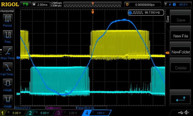 What about low and high side? This is the key area to my mind. Yellow = lowside Vgs, Dark Blue is high side Vgs 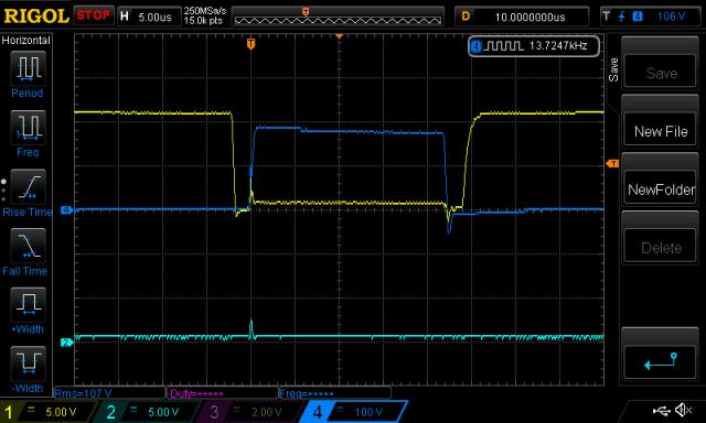 Nice. highside Vgs Vertical scale is incorrrect. Still a tiny bit of shoot through, but not too much. 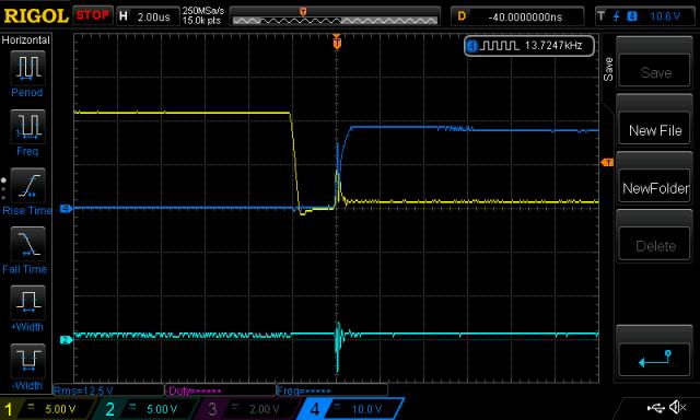 Clearly there is some but not too much shoot through. The dead time is 2uS, quite long compared with the usual settings we have with the EG8010. Here it is under load (170W) 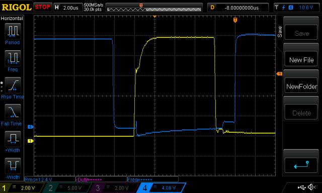 Very clean gate voltages. No ST here. But there is some elsewhere.. 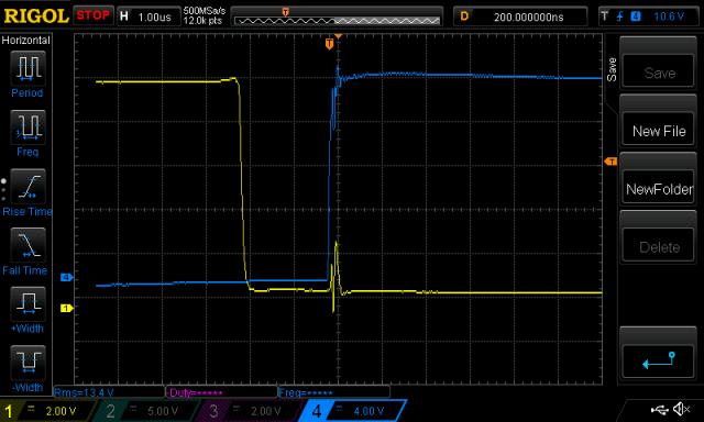 A little clearer capture shows the short duration of the event. All dv/dt caused. This is curious. The high side has a short pulse, well into gate threshold territory. But it's a short period of time when ST occurs. All OK. 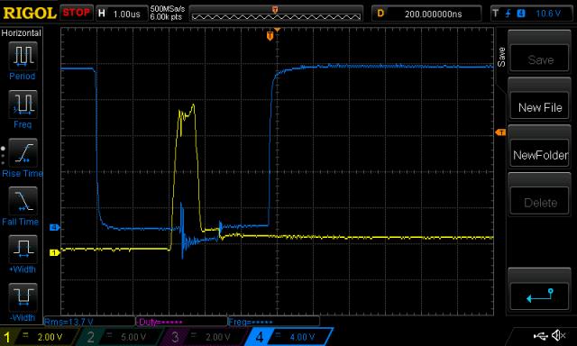 The PWM frequency was determined. May as well while I can. It's 19kHz 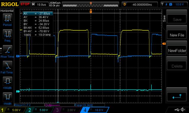 Using the same setup, but substituting the Mad control board with the PJ control board yielded lots to think about. Same testing conditions as above. 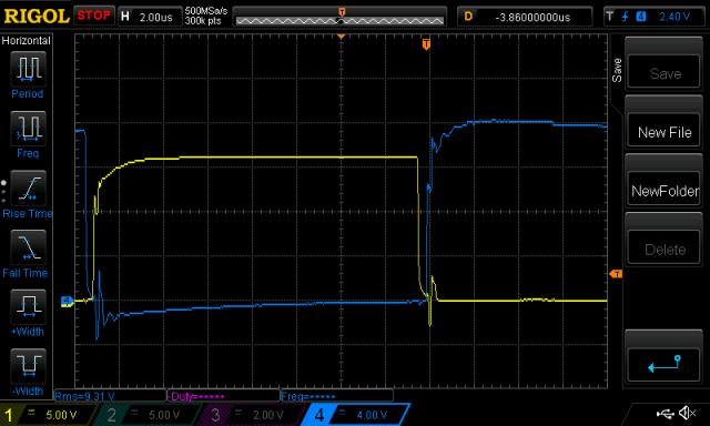 Immediately we can see the 500nS dead time. And significant periods of time in dv/dt caused shoot through. closer in time.. 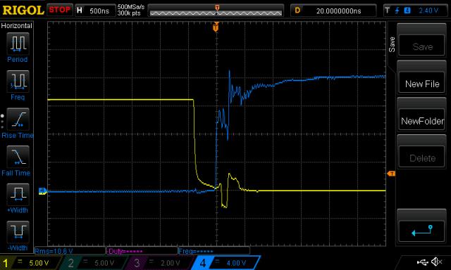 This is ugly. The low side gate is pulled up, well into Vgs threshold and stays there. The board uses IRF3710 MOSFETS and Vgs threshold is 2 - 4V. Did I tell you the test setup now is making a bit of noise? 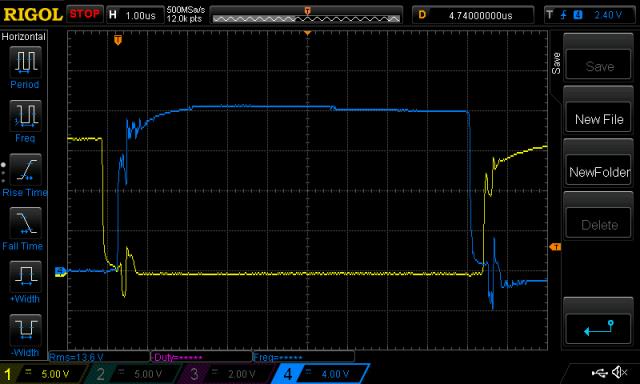 Not good. Shoot through is happening on both LOW->HIGH and HIGH->LOW transitions of the 1/2 bridge. The final one here was enough to cause my post recommending Ben and Amber don't run this board on a PJ power board. 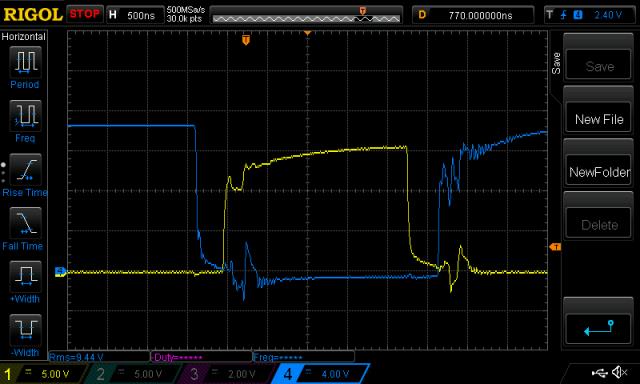 And no prizes for guessing the idle current was high. 1.51A at 52V I did not want to test this under load. No point and I don't want to break the nice PJ power board. Thoughts and comments welcome as always. Oh look, I see it's Beer O'clock. wronger than a phone book full of wrong phone numbers |
||||
| renewableMark Guru Joined: 09/12/2017 Location: AustraliaPosts: 1678 |
Interesting, so how does the Mad control board perform on the Mad power board? Cheers Caveman Mark Off grid eastern Melb |
||||
| poida Guru Joined: 02/02/2017 Location: AustraliaPosts: 1391 |
much better than the PJ power board. wronger than a phone book full of wrong phone numbers |
||||
| renewableMark Guru Joined: 09/12/2017 Location: AustraliaPosts: 1678 |
The slow totems protect the fets? Cheers Caveman Mark Off grid eastern Melb |
||||
| renewableMark Guru Joined: 09/12/2017 Location: AustraliaPosts: 1678 |
Might be time to test those ferite beads? Cheers Caveman Mark Off grid eastern Melb |
||||
| poida Guru Joined: 02/02/2017 Location: AustraliaPosts: 1391 |
More like the totem pole drives protect the gate drive IC outputs. Not as a primary function, but as a very useful side effect. wronger than a phone book full of wrong phone numbers |
||||
| noneyabussiness Guru Joined: 31/07/2017 Location: AustraliaPosts: 506 |
I know the original PJ board had 47ohm gate resistors, maybe that is slowing down the transition enough to clean up waveform. However greater dead time is needed to compensate. More, combination is the key than anything I think it works !! |
||||
