|
|
|
|
 Print Print |
|
|
| PicAxe based Pump Controller. |
|
I have a 5000
litre water tank next to the workshop, and it collects
rain water from the workshop roof. 5000 litre's is enough
to last me about 3 weeks, and with the rain we've had
I've being using rain water for the last 4 months. I
also have a jet pump and bore to supply water when there
isn't enough rain.
There is also a 1000 litre header tank
up on the hill behind the house. Its about 12 meters
above the ground floor, so provides heaps of water pressure.
To pump water from the main tank to
the header tank, I use a combination of wind driven
pump, and a 12v electric pump. The windmill pumps about
100 litre's per day.
The 12v electric pump is supplied from
the batteries kept charged by my generating windmills,
and uses a float switch in the header tank to switch
the pump off/on as needed. The float switch is about
1/4 way down the header tank, its there to keep the
tank at least 3/4 full, the wind pump filling the rest.
I originally used the float switch to
operate a relay for the electric water pump, but this
proved a bit erratic. As the tank level rose the float
switch would bob around and switch the pump off and
on every few seconds. This was a bit harsh on the poor
old pump, and could last several minutes.
So I designed this little pump controller.
|
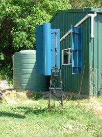
The water
pumping windmill, based on the blade design by Ed Lenz.
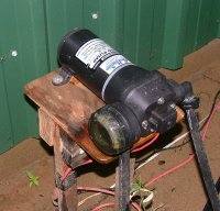
12v water pump.
|
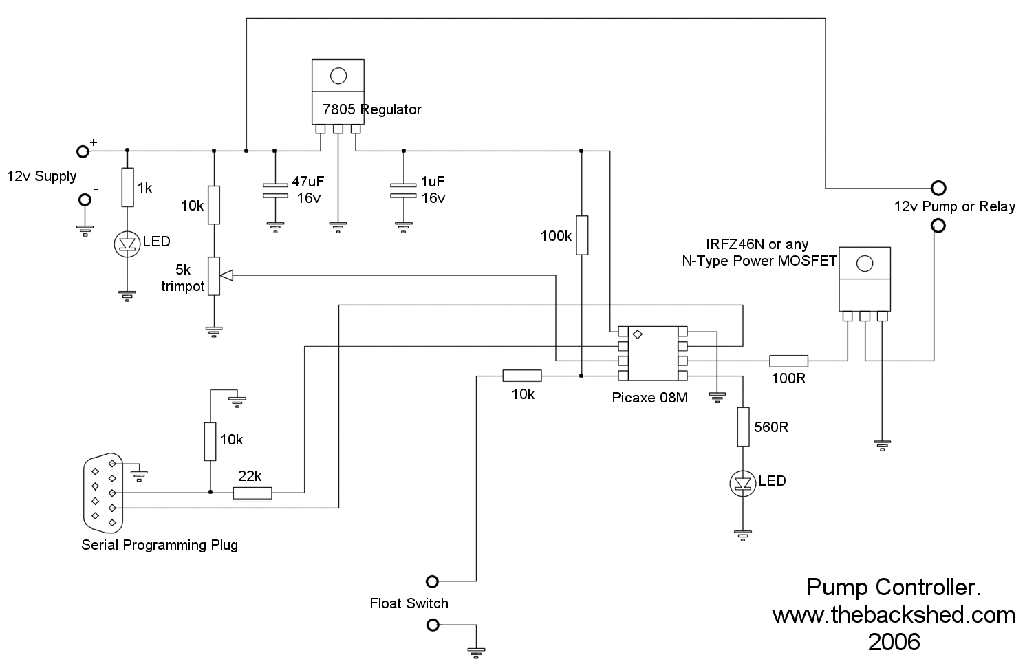
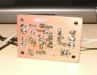
To the right is the circuit diagram.
Its a pretty simple circuit based on a PICAXE chip (
have I said how much I love these things? ). Click on
the circuit to show full size.
There are 3 connectors: 12V DC input
( Battery ); Float Switch; Pump or Relay.
|
 |
I wrote the program in the little chip
to follow these rules.
1. If tank level low, turn on pump for
30 seconds and check level again. Continue to check
level every 30 seconds.
2. If tank then becomes full, run pump
for a further 60 seconds, then turn off. This gets past
the bobbing float period.
3. If the pump has being running for
more than 30 minutes, turn pump off, flash the LED once
every couple of seconds. This means it has taken too
long to top up the tank, so there must be something
wrong, ie Main tank empty, leak in the line, float switch
stuck. You need to turn the controller off and on to
get back to normal operation.
4. If pump is on and battery voltage
drops below 11 volts, turn off pump, flash led twice
every couple of seconds, and wait for 20 minutes. After
20 minutes, check battery voltage again, if recovered
enough, turn pump back on. This saves the battery, gives
it a chance to recharge before starting pump again.
|
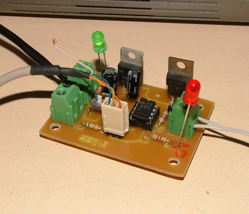
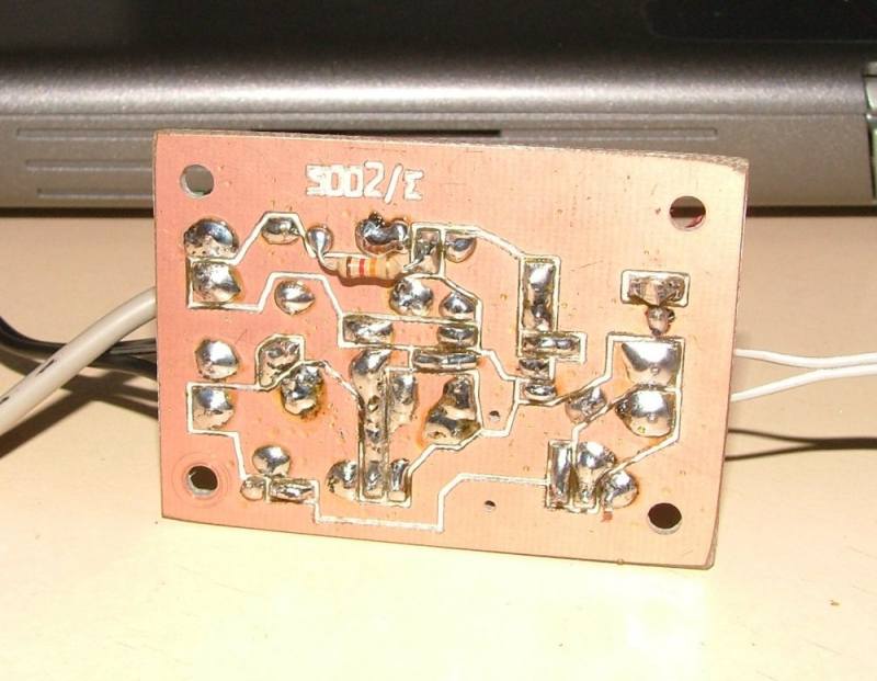
I used my CNC router to
make my circuit board. The CNC does a good job, sure
beats vero-board or etch pens and ferric chloride.
The only adjustment is the low battery
pot ( 5k ). To set this, I used a variable power supply
adjusted to 10.5 volts, and turned the pot until the
controller went into low battery mode.
The controller will come back online
after 20 minutes and if the battery has reached over
11.5 or so volts. This is adjusted in the software and
should only need to be set once.
If you want to use the controller for
24 volts, replace the 10k resistor in series with the
5k pot with a 22k resistor.
While the power MOSFET can handle the
pump current ( about 10 amps ), I use it to switch a
relay that in turn drives the pump. If you intend to
use a mains powered pump, then you must use a relay
to isolate the electronics. |

|
Click here to download the PICAXE code.
|
|
|
|
|
|
|