|
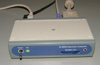
Introducing the Maximite
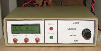
This little box is a complete
computer, programmed in BASIC,
and you can plug in a screen and
keyboard. Plus, its got 20 I/O pins
to experiment with! Comes as a
kit for $79.95AU
|
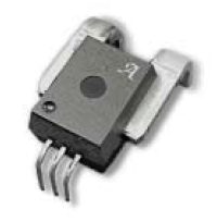
| Using the Alegro current sensors. |
|
I've used the Alegro current sensor chips in a few projects, and thought I would share a few tricks I've learned from my own projects and contributed by others.
The Alegro chips make measuring current in a micro controller based project a much easier task compared to other current measuring techniques, like shunt resistors. They can be sourced for under $20 on ebay.
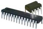
The chips come in a few flavours, but generally all look and behave the same. There are 2 large pins, these carry the current, and 3 other pins to power the internal electronics and provide a output. The output is isolated, and proportional to the current measured. If the chip is a bi-directional type, the output voltage would be half the supply voltage if no current is flowing, and swing either side of this mid point depending on current value and direction. So if the supply voltage is 5v ( typical ), the midpoint, 0 amps, would be 2.5v. Unidirectional types have a output of 0.1 of the supply voltage ( 0.5v for a 5v supply ), and this increases with current. |
|
The Alegro chips are very sensitive and react quickly to the slightest change in current. In fact, they are too sensitive for most applications, so we need to add some filtering to the output, CF and RF in the circuit above. For my own projects I've used a 10k resistor and 22uF electrolytic for the capacitor, but tantalum capacitors are better suited, and values closer to 100uF will be needed in some cases.
When you buy a Alegro chip, you need to choose a model based on the maximum current you expect to pass through the device, typically 50 to 200 amps. You can also add a shunt to bypass some of the current around the chip, increasing its reading value. There is a interesting article about this here.
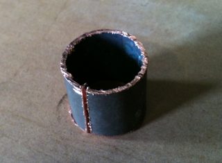
Mounting the Alegro chip.
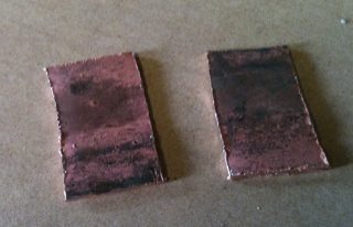
| I used a short length of 1inch copper pipe, but any copper sheet will do, providing its thick enough, about 1mm in this case. |
 |
Flattened out and cut into two.
 |
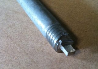 |
Next I made a punch from an old bolt. The punch is shaped to suit the Alegro legs. Using a hammer and piece of hardwood ( into the end grain ) made the job easy. Thanks to Pete for that tip.
|
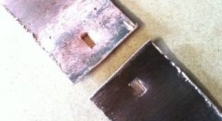
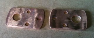
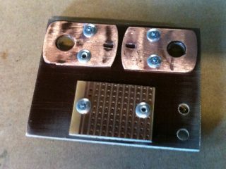
Next I drilled and shaped the copper plates like this, and sanded the copper so it was clean. To the right you can see the plates and a piece of veroboard riveted to some fibreboard. The fibreboard is perfect for this sort of job, but any tough heat resistant material would do
|
 |
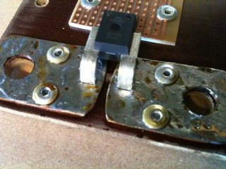
Then I tinned the copper plates, fitted the Alegro and soldered in place. For this sort of soldering, you need a big soldering iron, 100 watts or more, with a big tip.
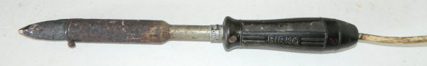
The copper plate will tend to pull the heat away from a smaller iron tip, so the bigger the tip the better. It means you can make a nice solder joint in a few seconds, reducing the heat stress on the Alegro chip. I wouldn't attempt this with a smaller soldering iron. |
 |
 |
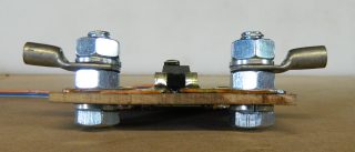
| Here is a side view so you can see how the bolts are mounted. The spring washers under the fibreboard are a must. |
 |
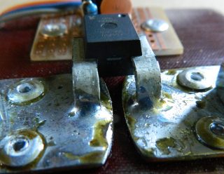
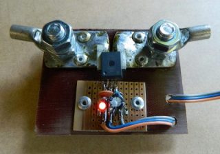
| After it cooled down, I mounted the other components. The LED is there for show, not needed. |
 |
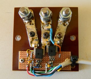
Here is another one I built using two unidirectional Alegro chips. This time I used copper bar, 10mm wide and 5mm thick approximately. I used a mill to machine the slots for the Alegro pins.
This one will be used to separately monitor amps into and out of a 50 volt battery bank. The blue heat shrink and orange wire is a battery voltage sense wire. |
 |
Using the Alegro with a micro controller
One problem with using the Alegro coupled to a micro controllers analogue input, is the small fluctuations around 0 amps. The Alegro output for 0 amps is either 0.5 of the supply voltage for the bidirectional types, or 0.1 of the supply voltage for the unidirectional type. Our software can allow for that by adding a preset offset the reading. If 0 amps measures 2.5 in the microchip, then we just need to subtract 2.5 from the reading to get the actual amp reading, any value above or below 2.5 will be plus or minus amps.
The problem is any small changes in the supply voltage will change this offset from the Alegro, and our software's fixed offset will be wrong. This error may only be small, a few hundred milliamps, but these can add up over the course of time to several tens of watt hours. Say for example we are managing a 48 volt battery bank, and we get an error of 0.1 amps due to power supply drift. That's 5 watts of error, 120Wh for a day!
There are a couple of tricks I've used to get around this problem. One way is to use software to ignore any small changes around 0 amps. In this example, we ignore any amp value between +0.2 and -0.2, pin 1 is our input. I'm not worried about multipliers/calibration in this example.
AmpOffset = 2.5
AmpReading = pin(1) - AmpOffset
if AmpReading > -0.2 and AmpOffset < 0.2 then AmpOffset = 0
Another way is to measure the supply voltage with a spare analogue input, pin 2 in this example. We still need a Offset value, 2.5 in this example, and we still need the last line that that filters out slight changes around 0 amps. Here we are using a
AmpOffset = pin(2) - 2.5
AmpReading = pin(1) - AmpOffset
if AmpReading > -0.1 and AmpOffset < 0.1 then AmpOffset = 0
|
|