|
|
| Gizmo's Picaxe based Windmill Controller/Charger. |
Page1 | 2 |
(Works
with solar too!)
This project
is a work in progress. Page 1 describes the charger I originally build in 2006, and page 2 is the updated version in 2010. The charger was designed to regulate
the output from my big F&P windmill. And I wanted
to make something useful with a PICAXE chip.
On this page you will find the circuit
diagramme and programme listing, but I offer no support
for this project, it is aimed at those who have some
experience with PICAXE chips, programming and electronics.
Unless you have some experience in these, I wouldn't
recommend you try this project.
You will also need to design your own
circuit board, I used veroboard and its a bit messy. |
 |
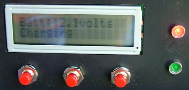
The charger
will work on 12 or 24 volt systems, and uses power MOSFETS
to do the heavy current switching. An LCD screen displays
the battery voltage, current and menu options. The menu
lets you set the charge voltage, load voltage and low
battery alarm. When the battery voltage exceeds the
preset load voltage, the windmill output is switched
to a load. When the battery voltage drops below the
preset charge voltage, the windmill is switched back
across the battery. If the battery voltage drops below
the battery alarm voltage, the charger will beep continously.
If you loose power the PICAXE will remember the values
you set. |
 |
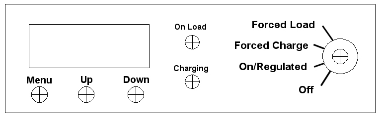
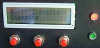
To set the charge
and load voltage, press the menu button. The screen
will ask you to set the charge voltage using the up
and down buttons. As you press the buttons the voltage
will change in 0.1 volt steps. Pressing the menu button
again and the screen will ask you to set the load voltage.
Press again to set the Low Battery alarm value. Press
the menu button again will return to normal operation.
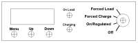
The power switch is a 4 position dual
gang type. Position 1 is off, position 2 is normal operation,
position 3 is forced charge ( Boost ), and position
4 is forced load. In forced charge, the windmill power
is fed straight to the battery with no regulation. Forced
load dumps the windmill across the dummy load, handy
to shut down the windmill. |
 |
| The controller
sends out data via the serial port. This include the battery
voltage and current. I did have a little monitor program
you could download to display this on your computer, but
software changes in the PICAXE mean I will need to rewrite
the monitor program. Stay tuned for future updates. |
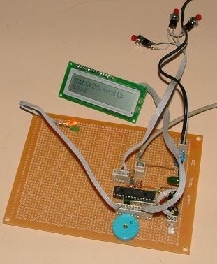
The circuit
( Click to enlarge ) was made using parts from my junk
pile, so you may have a better understanding of electronics
than I do and want to change values to suit. Please
do.
Click here for a PDF version that may print better on A4 size paper.
The PICAXE used is a 28X, needed due
to the larger program and extra outputs. |
 |
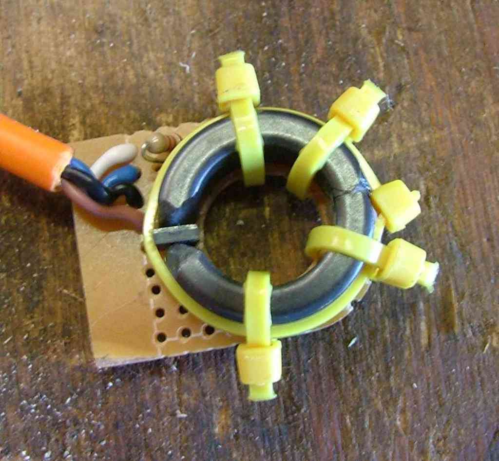
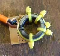
The current
sensor is made by cutting (breaking) a iron-powdered
toroid core in half, slipping in a hall effect device
and gluing back together. This photo is a earlier attempt.
You can see how the hall sensor sits in the magnetic
path. I reshaped the ends of the core to concentrate
the magnet flux through the hall sensor.
The easiest way to split
the core is to file a grove around the place you want
to spilt it, and then lever the two halves apart. They
shatter easily, dont drop it. |
The hall sensor used is a UGN3503U.
It has a analogue output, proportional to the magnet
flux. Dont use the hall sensors from the F&P motor,
these have a logic out and are latching. |
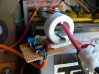
| And
this is the working sensor board. The 741 op amp and associated
components are mounted next to the core. Adjustment of
the sensor if via two pots. The 500 ohm is adjusted to
zero the amp meter, and the 100k pot adjusts gain. And
it a real pain to get them right. Once you adjust one
you need to then adjust the other. You have to make these
fine adjustments back and forth between the pots until
you get it right. You can also adjust the zero point in
the software, more on this later |
 |
The hall sensor
has a output voltage of about 2.5 volts, plus or minus
0.1 volts, depending on the current through the core.
This is amplified by the 741 to a range of 2 to 3 volts.
The picaxe converts this to a number range of 0 to 255,
with 128 being the zero point ( no current ). This gives
us a range of -128 to +128. In the software in the DisplayAmp
routine you will see 128 used in some maths and if-then
statements. By changing the value 128 up or down, you
are adjusting the zero point.
You can set up the display to range
from -12.8 to +12.8 amps, or -128 amps to +128 amps.
This is done by removing the decimal point in the code,
and adjusting the 100k pot ( gain ) on the sensor board.
Remove the following lines in the DisplayAmp to remove
the decimal point...
byte = 46
Gosub SendDataByte
|
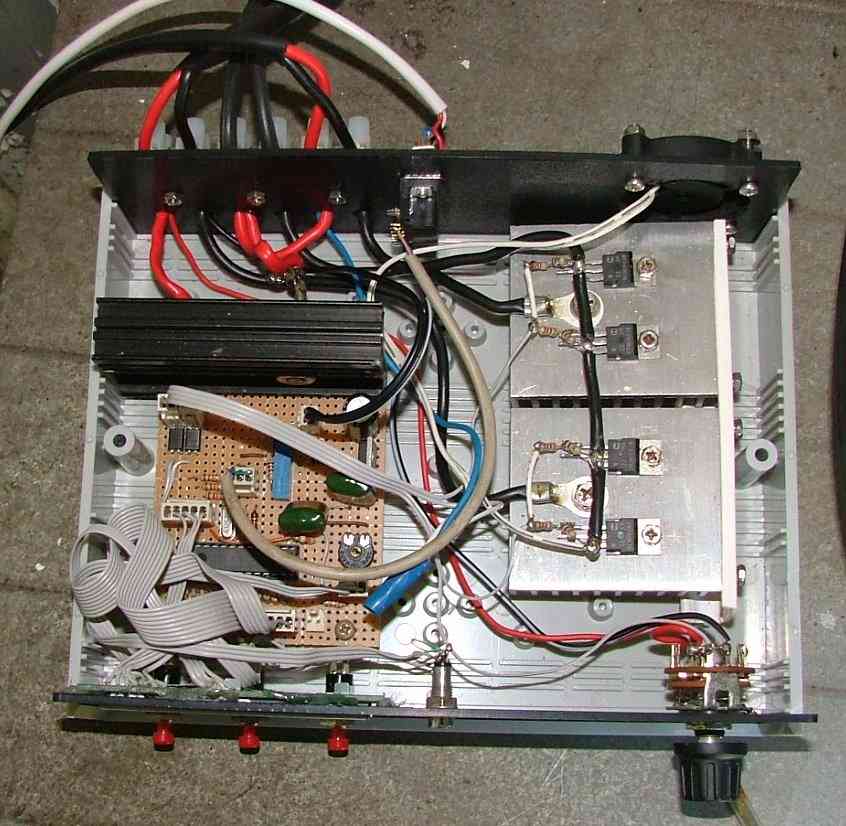
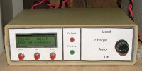
This is my finished charger. Not pretty,
but working. I plan to make up a facia cover to stick
on the front face. Should make it look a little more
professional. I recently replaced the LCD display with
a fluorescent display ( VFD module ). The new display
is almost pin for pin compatible with the LCD display,
and looks better. Made by Noritake, model CU16025ECPB-W6J, www.noritake-itron.com.
A big thankgs to Geoff for the module.
|
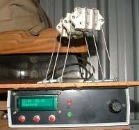
You can see my dummy load in this picture,
3 modified jug elements, and they get HOT! |
Click here to download the PICAXE code.
Notes:
The charger is a work in progress, but
it does work, and has been regulating my battery bank
( 2 car batteries connected in parallel ) for over a
year now.
Electrical Issues-
- The 1k drive resistors to the gates
of the mosfets should be a lot lower in value to ensure
clean switching, like 47 ohms or less.
- For a higher power charger, say over
20 amps, I would look at using relays instead of mosfets.
My mosfets get hot with 20 amps.
- You can replace the WE840 optocouplers
with PC817 or common 4N25 chips. On the circuit the
WE840 is shown as a PNP, this is a mistake by me,
they are actually NPN
- The current measuring circuit ( op
amp, hall sensor ) is not very accurate, give or take
a amp at 10 amps. I've since started using current
transducers, available for $20 to $40 from www.rsaustralia.com,
these are a lot more accurate.
- The controller will work just as
well as a solar regulator, only we dont need the dump
load, so just leave out the dump load circuit ( including
the MOSFETS ) if you only want to use the controller
on a solar panel.
Thanks to the guys that pointed out
these problems and made suggestions.
 Next - Updated version Next - Updated version
|
| |
|