 |
|
|
Site Navigation
Projects & Information
»General Information»Wind turbine Projects »The F&P Smartdrive »Electronic projects »Microcontroller projects »Miscellaneous Kits & Parts
»Basicly Natural Pty Ltd»PVC & Aluminium blades »Scale model farm windmills »Price Watch Discussion Forums
Handy Links
»Wind»Solar »Electric Vehicles »Electronics »Micro Controllers »General Interrest About TheBackShed Getting Started Privacy Policy |
Making your own LCD Panel Meters
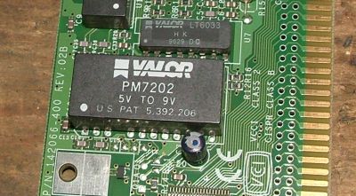
Now these need 9 volts to run, but this 9 volts must be isolated from the voltage you are measuring, ie, you can not measure the meters own power supply. So we need a floating or isolated 9 volt power supply to power the meters. Oatley Electronics sell a little isolated power supply board for just this reason, http://secure.oatleyelectronics.com/files/K212notes.pdf, and in the March 2007 edition of Silicon Chip magazine there was a article all about it and using these meters as a volt/amp meter. But I found a cheaper way. The old network cards, the ones with the BNC
coax connector, have a 5 to 9 volt isolated inverter on the
circuit board. If you have one of these old network cards
in the junk box, have a look for the model number on the inverter
and do a google search. This one is a PM7202, and I found a PDF datasheet
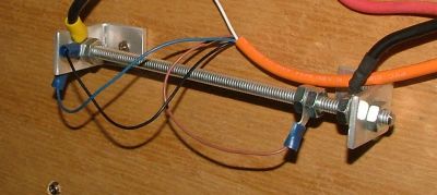
to match. As you can see, these inverters are tough little buggers, and built to last. So remember next time you throw away those old computer cards, check for any networkcards with the inverters on board. In fact there are lot of goodies on old computer cards and main boards, always have a close look before dumping. Now the inverter has a input voltage of 5 volts, so we need to add a 5 volt regulator, such as a LM7805, and a couple of filter caps. This, with out little inverter, will give us a isolated 9volt power supply for the meters. Measuring our battery voltage is easy, we just connect the meter across the battery terminals. We need to set up our panel meter to read 20 volts full scale ( or 200 volts full scale if we are using a 24, 48 or higher voltage battery bank ), and this is done by changing a couple of resistors on the back of the panel meter. The instruction booklet that came with the meter should explain how this is done. To measure current we need to use a Shunt Resistor. A shunt resistor is a low value resistor placed in series with the battery bank. And I mean LOW resistance, like 0.01 ohms. You could use a length of wire as a shunt resistor, but I used a length of 6mm ( 1/4 inch ) threaded rod. Using threaded rod means I can adjust the amp meter reading by moving the connections along the rod.
The rod shown is about 170mm long, and I found 120mm was the magic point to give a accurate reading on the panel meter. As my panel meter reads 0.2 volts full scale, and this shunt gives 0.001 volt per amp, then my meter can read up to 200 amps. Ok, here's the complete circuit, you can click on the image to see full size. As my meters were mounted on the battery cabinet door, I used a length of 4 core cable between the meters and battery bank to make the installation easier and neater. Make sure you use a two separate wires for the shunt -ve and battery -ve terminals, as noted on the circuit diagram, or the amp meter will not display correctly ( there will be a phantom amp measurement of several amps if you try to use one wire as a common -ve ).
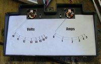
A bit of nostalgia.
I eventually decided to turn it into a amp meter. I designed and lasercut a timber box from 9mm plywood, gives a nice aged look. Then I took the meter apart to get access to the meter scale and mechanism. The meter scale was scanned into PaintShop using a flat bed scanner, a new scale drawn up to read amps, printed out and glued over the old scale. By scanning in the old scale, I made the sure the new scale would fit exactly into the meter case. I then adjusted the meter movement to convert the meter into a centered meter, the meter would originally stop at the left. With careful adjustment of the springs I made the meter center, and modified the zero screw on the front case to adjust the center position. It was a fiddly job, and one slip would have stuffed the meter for good. To finish off the meter I added a shunt resistor made from a strip of 2m zinc plate, a couple of trimpots, and a rotary switch to select between +-10 and +-100 amps.
|
||
 First
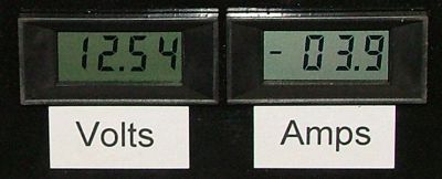
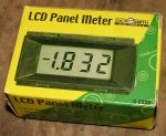
up I bought a couple of those cheap LCD panel meters from
Dick Smith for about $12 each, though most electronic component
outlets will carry then. The meters include a datasheet with
details on changing the voltage range, and moving the decimal
place. My meters were factory set to read 200mV full scale,
but some come ready to measure 20V
First
up I bought a couple of those cheap LCD panel meters from
Dick Smith for about $12 each, though most electronic component
outlets will carry then. The meters include a datasheet with
details on changing the voltage range, and moving the decimal
place. My meters were factory set to read 200mV full scale,
but some come ready to measure 20V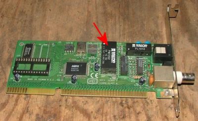
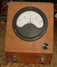 This
old meter was once a db audio meter from the old Telecom Telephone
exchange I worked at many years ago. I saved it from the rubbish
bin, back then Telecom, been a typical government agency,
had a stupid policy of destroying anything it threw out. So
any electronics had to be smashed before it was dumped. Like
I said, stupid. Anyway I saved this meter because it was very
old and I liked the look of it. It then spent several years
in a box in my workshop, waiting for a use worthy of its age.
This
old meter was once a db audio meter from the old Telecom Telephone
exchange I worked at many years ago. I saved it from the rubbish
bin, back then Telecom, been a typical government agency,
had a stupid policy of destroying anything it threw out. So
any electronics had to be smashed before it was dumped. Like
I said, stupid. Anyway I saved this meter because it was very
old and I liked the look of it. It then spent several years
in a box in my workshop, waiting for a use worthy of its age.