|
|
|
|
 Print Print
|
|
|
| Understanding Staggered Stators. |
|
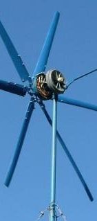
Staggered Stators is a term we use to describe an alternator wired up into 2 or more different circuits, each with a different cut in speed. The "stagged" outputs from these circuits are commoned together to provide a charging current that better matches the wind speed. This is a technique used in many small commercial wind turbines, and here we discuss the same technique on a home built windmill using the F&P Smartdrive as its alternator.
 |
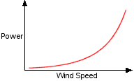 First up, we need to understand wind power. If we double the wind speed, we don't double the power we can harness from it ( or push through it ). The power is actually cubed. To put it simply... First up, we need to understand wind power. If we double the wind speed, we don't double the power we can harness from it ( or push through it ). The power is actually cubed. To put it simply...
Power = Windspeed3
So if a hypothetical windmill can get 10 watts from a 10kmh wind, then it could get 80 watts from a 20kmh wind, or 270 watts from a 30kmh wind. Please note, all figures used on this page are simplified and don't represent real world data.
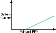
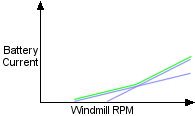
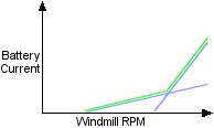
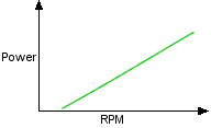 Our typical windmill alternator, on the other hand, has a linear output. If the windmill RPM doubles, so does the output power. The wind power curve and alternator power curve mismatch, so the alternator is built to run in a "band" of wind speed where it can make the most power. There is more power in high winds, but these happen less often than low winds. If we built a windmill to only use high winds, we would miss out on the more common low wind power. If we build a windmill to use low winds, we miss out on the big power in high winds. Our typical windmill alternator, on the other hand, has a linear output. If the windmill RPM doubles, so does the output power. The wind power curve and alternator power curve mismatch, so the alternator is built to run in a "band" of wind speed where it can make the most power. There is more power in high winds, but these happen less often than low winds. If we built a windmill to only use high winds, we would miss out on the more common low wind power. If we build a windmill to use low winds, we miss out on the big power in high winds.
So how do we take advantage of high and low winds? One way is by using different alternators, each designed to run in a different band of wind speed.
|
|
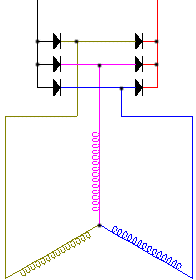
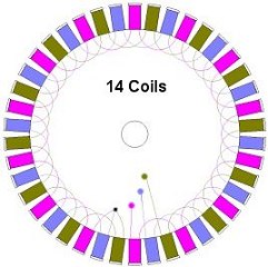
This is a standard F&P alternator, a 1X14C ( 1 times 14 coils ). It has many coils in series, so has a low cut in RPM and will start making current in very low winds. Due to its high coil resistance, its current/power ability is limited, so it cant make high power in high wind.
|
 |
 |
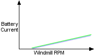
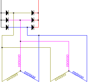
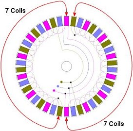
If we electrically split the alternator in half, and connect the two halves in parallel ( a 2X7C ), we will double its current capacity, but also double its cut in speed, meaning we are missing out on any power we could be making in low winds.
|
 |
 |
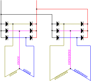
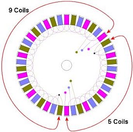
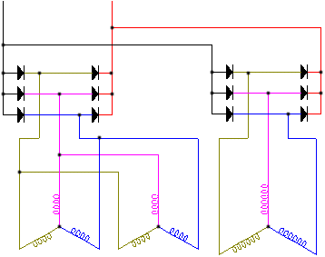
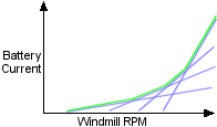
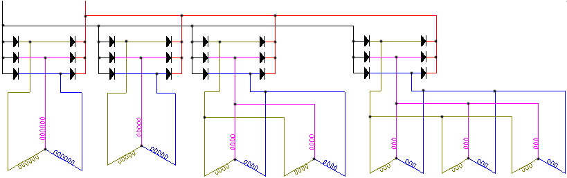
So what if we use two circuits of different coil counts? Each circuit will have a different cut in speed. In this example, in light winds the 9 coil side will start making power, without loading down the windmill too much. As the wind increases, the 5 coil side will start making power and this will add to the current already produced by the 9 coil alternator. Our alternator power curve is starting to follow the winds power curve. This alternator is a 1X9C 1X5C. Note we need to use separate bridge rectifiers for each circuit, as they run at different voltages.
|
 |
 |
We can try different combinations to get a power curve that works best with our wind conditions and turbine performance. Here we have one 6 coil circuit and 2 4 coil circuits in parallel.
Its a 1X6C 2X4C.
|
 |
 |
 A real life example. A real life example.
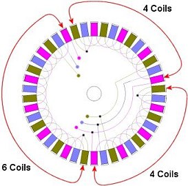
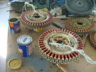
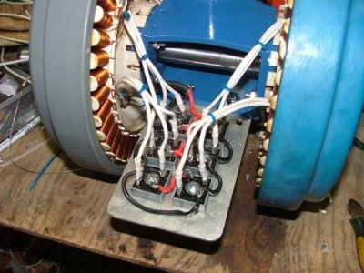
Here is a staggered stator build I put together a couple of years ago. Its a dual stator windmill, so I had lots of coil combinations to play around with. I ended up using a 1X6C 1X5C 2X4C 3X3C configuration. This gave 4 different cut in speeds. The windmill starts producing power in lights winds and has a smooth output up to its furling speed at about 17 amps. The windmill it replaced had a maximum output of 20 amps, but spent most of its time making no power, because it was not designed to use low wind speeds. This new staggered stator windmill makes more power over the course of the day, because its using low winds and can still make good power in high winds.
Staggered stators was originally discussed on these two forum threads.
http://www.thebackshed.com/windmill/forum1/forum_posts.asp?TID=749
http://www.thebackshed.com/Windmill/FORUM1/forum_posts.asp?TID=751
Another way to make use of low winds and better match high wind power is to use capacitors, as described in this article by Gordon.
Glenn.
|
|
|
© TheBackShed 2011
|