
|
|
Forum Index : Electronics : A newbie ozinverter build
| Author | Message | ||||
Madness Guru Joined: 08/10/2011 Location: AustraliaPosts: 2498 |
Do you think those LM2596HV step down volatage converters will stand up to solar power usage? My battery bank is at 59V on absorb charge and 54V for equalization. There are only 10 types of people in the world: those who understand binary, and those who don't. |
||||
| tinyt Guru Joined: 12/11/2017 Location: United StatesPosts: 431 |
The pre-assembled LM2596HVS DC-DC I bought from alliexpress has an input capacitor marked 100 uF 63V. The chip is marked LM2596HVS ADJ, not sure who is the manufacturer. TI datasheet says that absolute maximum input voltage is 63V and recommended operating max input voltage is 60V. My benchtop power supply is a dual 30V 1.5A which I connected in series. With the two in series I was able to get 62.1V with the coarse and fine dials at max. It is this voltage that I am now feeding my experimental board which has three LM2596HVS chips for close to an hour now and so far no smoke. Current draw is 0.06A (no fans, no power mosfets). When I powered it for 24 hours (no fans, no power mosfets) the hottest of the three chips measured 78 deg C. It is hot to the touch, but the datasheet says its max operating temp is 125 deg. C. But because it just relies on the small PCB copper area for heat dissipation, I plan to solder a piece of copper sheet to the chip tab for additional heat dissipation. |
||||
| Madness Guru Joined: 08/10/2011 Location: AustraliaPosts: 2498 |
Isee many of them with different voltage ratings. I just order some different ones that are supposed to be good for 90V and 3A output. There are only 10 types of people in the world: those who understand binary, and those who don't. |
||||
| tinyt Guru Joined: 12/11/2017 Location: United StatesPosts: 431 |
Good find, and it has higher efficiency. Maybe it can be hacked for higher than 12V output for the mosfet drivers. Will order some - shipping cost for 2 to US is $5.67, maybe worth it. Thanks. |
||||
| Madness Guru Joined: 08/10/2011 Location: AustraliaPosts: 2498 |
There is 5, 9 & 12V versions, I have ordered several voltages to compare for exactly that reason as I want 18V for driving MOSFETs. A low cost isolated DC-DC converter would be good too but they seem to be very expensive. There are only 10 types of people in the world: those who understand binary, and those who don't. |
||||
yahoo2 Guru Joined: 05/04/2011 Location: AustraliaPosts: 1166 |
if you really need something to work, I suggest considering Devcon I use it sparingly, its expensive but it is usually stronger and harder wearing than the original. I keep a small piece of perspex for mixing the parts I'm confused, no wait... maybe I'm not... |
||||
| Madness Guru Joined: 08/10/2011 Location: AustraliaPosts: 2498 |
Devcon is amazing, used to be able to get it at supacheap before they changed there stocked items, would like to know where to get it now. I used it once to repair a corroded outboard motor pump housing which had a rubber impeller running inside it at engine RPM, worked perfectly and never let go. I thought JB weld was much the same product? There are only 10 types of people in the world: those who understand binary, and those who don't. |
||||
| tinyt Guru Joined: 12/11/2017 Location: United StatesPosts: 431 |
I finally finished the roof install of my solar panels. Now I can go back to the inverter. I found a leftover 3/8" dia. copper tubing for the DC-DC heatsink. I pre-tinned a section:  Then I fabricated the heatsinks.  And soldered them on the LM2596HVS tabs. 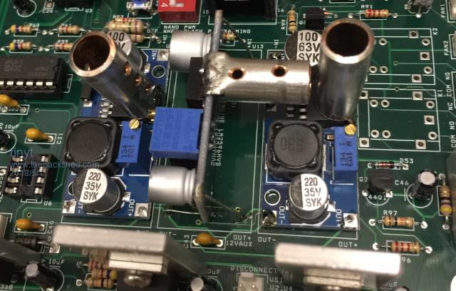 Again using a thermal probe on the hottest LM2596HVS, the temperature dropped by 10 deg. C. But when I get the better DC-DC converter that Madness found, I will replace the LM2596HVS pcbs with them. |
||||
| tinyt Guru Joined: 12/11/2017 Location: United StatesPosts: 431 |
Worked on the heatsinks. Drilled pilot holes first: 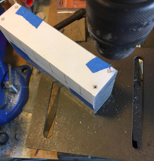 Then used correct size drill and then tapped the holes: 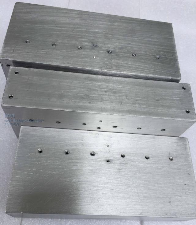 |
||||
| tinyt Guru Joined: 12/11/2017 Location: United StatesPosts: 431 |
An alternative to buying or re-using real heatsink is to buy aluminum angle bar and fabricate it. This is 1.5" x 1.5" x .125" angle bar purchased from a local home buider store (Home Depot). I think it has enough mass to absorb the heat from the mosfets and enough surface area to dissipate to surrounding air. 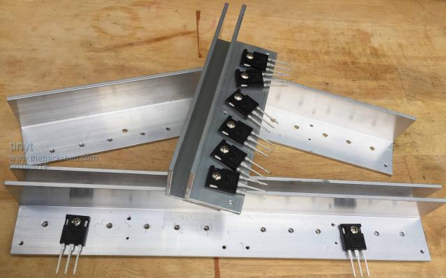 I am going to try this first. If it is adequate enough, the re-design of the PCB will be smaller since I can move the heatsinks closer to the large capacitors. |
||||
| Tinker Guru Joined: 07/11/2007 Location: AustraliaPosts: 1904 |
tinyt, you run a risk with these angles in my experience. I have experimented with 2" x 2" x 0.25" alu angle at the beginning and still managed to blow Mosfets. These things have two *very* tiny (hair size) wires inside from the drain leg to the substrate. There is no way these could carry the quoted amperage. So, it is essential that any heat build up is prevented by *very* good heat sinking. I use no insulating washers either for that reason. Your angles might work for tiny loads, like a couple of hundred watts but if you plan to switch two or three kilowatts suddenly on you need a beefy heat sink with a large fin area and a thick base of at least 5/8" or better 3/8" thick. Actually, you do *not* want the heat sinks close to the large capacitors, these capacitors live a lot longer running cool. I have mounted my capacitors on the opposite side of the PCB for that reason. This also made laying out the heavy current tracks easier. Talk to your local solar installers and see if they have a junked grid tie inverter. You can salvage a very decent heat sink from even a small 1KW unit and a brilliant one from a 3KW inverter. Klaus |
||||
| tinyt Guru Joined: 12/11/2017 Location: United StatesPosts: 431 |
Thanks Klaus. I will try it on small loads then. What mosfet part numbers were you using during your experiment? |
||||
| Madness Guru Joined: 08/10/2011 Location: AustraliaPosts: 2498 |
With no load at all you can run the inverter with no heatsinks at all. But this is only for initial testing and providing everything is running correctly, even leaving out the primary choke would cause overheating like this. I agree with Klaus any decent load and you are going to have hot MOSFETs. You can try it with what you have there and see what happens. If you can gradually increase the load while monitoring the temperatures you will soon see what will happens. The other heatsinks you have been working on will have probably close to 50 times the surface area. There are only 10 types of people in the world: those who understand binary, and those who don't. |
||||
| tinyt Guru Joined: 12/11/2017 Location: United StatesPosts: 431 |
Ok. I have made provision for heatsink mounted thermistors on all three. I will see how hot they will get for comparison. |
||||
| Madness Guru Joined: 08/10/2011 Location: AustraliaPosts: 2498 |
I would also use an infrared thermometer and read the temperature of the actual MOSFETs during your initial testing. There are only 10 types of people in the world: those who understand binary, and those who don't. |
||||
| tinyt Guru Joined: 12/11/2017 Location: United StatesPosts: 431 |
Hi Madness, I received my 4 pcs 12V units and the 8-pin IC has its markings scraped off on 3 of them. Maybe they forgot to do it on the fourth one. First line is marked SL3038 and second line is marked 1803 (maybe date code). Was not able to get SL3038 data sheet from the web. Tested one with the power supply at 63V. No load output is 12.45VDC. When loaded with 3 fans, the output dropped to 12.19VDC. Current draw of the 3 fans is 0.63A (7.67 watts). Current draw from the power supply is 0.14A (8.82 watts). Touch temperature of components is just barely warm. There are two resistors with silkscreen R7A and R8A. I assumed they are for output adjustment. Both of them are marked 3901 (3.9K ohms). I changed R7A to 2.0K and the output became 20VDC. I was happy. Then I placed a 55 ohm load (about 0.36A or 7 watts). Monitored the output, turned on the 63V power supply. No smoke but the DMM showed some reading, I am guessing 20, then quickly settled to 6vdc. Power supply current display is zero or below its range. Maybe wrong hack. Going to sleep now, too tired from bathroom re-modeling. |
||||
| Tinker Guru Joined: 07/11/2007 Location: AustraliaPosts: 1904 |
No problem. I use HY4008's. As mentioned, these Mosfets have tiny internal connecting wires and cannot tolerate a marked temperature difference between its case and the heat sink. The wires evaporate and the case explodes. You guess how I know that  . .Any heat needs to be sinked away as fast as its generated, so no hot spots occur. That requires a thick base heat sink or a fan going flat out when heavy currents are switched. Klaus |
||||
| tinyt Guru Joined: 12/11/2017 Location: United StatesPosts: 431 |
Thanks Klaus for the warning on using fabricated alum angle bars. But I am hard headed and I also want to experience blowing mosfets like you and the others so I that I can join the club and also never forget. On the 90V input DC-DC I am experimenting to raise the output to 18VDC: The first of the four, I changed only R7A and it failed when loaded. The second of the four, I changed R7A and R8A and it also failed when loaded. The third of the four, I was poking around with the DMM probe and damaged it. I was left with one 12VDC output. So I asked the vendor if they can make an 18V version, after several messages, they said they can only make 17.6VDC and not to exceed 30 Chinese watts, I ordered. By the way they increased the price now from $5/2pcs to $6/2pcs. Will see when the part comes in. Meantime I did more web search and found a schematic that is very close and made one with values changed for the ones I previously odered. Maybe I should have changed R5 and ZD1 also when I was experimenting. I don't know if this will be useful to anybody else, but here it is.  |
||||
| poida Guru Joined: 02/02/2017 Location: AustraliaPosts: 1389 |
For DC-DC converters that provide small power for my inverter(s) I use AC plug packs or power adapters. Some adapters work fine when fed 50V DC into the AC input. Some do not. I just keep looking in the box for another one that will work on 50V... So what if only one side of the diode bridge is working? I use the AC to 12V 1A adapter that came with a Western Digital external HD. Perfect for my job which is to power the inverter board, direct from the 48V battery. And the output is isolated. wronger than a phone book full of wrong phone numbers |
||||
| tinyt Guru Joined: 12/11/2017 Location: United StatesPosts: 431 |
Thanks poida, never thought of it. I have a few wall warts, most of them will probably work with 48VDC since our utility voltage is 110VAC. |
||||
