
|
|
Forum Index : Electronics : a new way to balance lithium ion battery
| Author | Message | ||||
| Tinker Guru Joined: 07/11/2007 Location: AustraliaPosts: 1904 |
Ok, I think its time I post an update to the LiPo charge balancing idea I poste at the beginning of this thread. Firstly, while the idea works now fine it was not without problems I had first to overcome. I'll talk you through them: The first relays I used had DPDT contacts, there are not many of these in PCB mount variety around and they are quite expensive. Unfortunately they did not last long - contacts burned out. Next I replaced them with SPDT relays, of course I needed twice as many (16) of them now. As a bonus it was easier to lay out the PCB for 16 relays BTW. I choose one with double the contact rating of the previous relay but still had failures. Thinking it was the inrush current of the capacitor I placed low ohm resistors in series. Only to watch them get very hot during the brief time the individual relay pair was on, fuses fitted in the lead to the cell also blew. So, something else must be causing this and, after a considerable time scratching my head  the penny finally dropped - it had nothing to do with the inrush current at all. the penny finally dropped - it had nothing to do with the inrush current at all.
A brief circuit description: a 4017 counter is clocked to sequentially step through its outputs. Each output drives the base of a PN100 transistor via a suitable resistor and a relay coil pair makes the collector load of each transistor. The relays operate in pairs to get the DP contact requirement. There is something fundamentally bad using the 4017 outputs that way, I wonder who can guess what it is? Hint, check the 4017 truth table. Next, who can guess how I overcome this, still using the 4017 IC and transistor relay drivers mentioned above? Anyway, its quite a simple solution and works well. I managed to find relays with an even bigger contact rating (30A) and, even better, just a quarter of the price. Look in the Altronics catalogue under automotive PCB mount relays. I also experimented with using 25F capacitors, they are quite a bit cheaper than the 100F type I started off with. The PCB was redesigned for the lot to fit into a UB2 size jiffy box, see picture below. 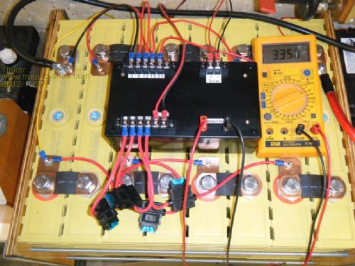
The sockets marked 'capacitor' connect directly to them. They allow to initially pre charge the capacitor to cell voltage before the sequencer is turned on. Then they provide a convenient place to monitor each cell voltage as the sequencer connects to each in turn - displayed on the multimeter shown. The electronics are powered from a 24V to 12V DC-DC converter which also runs other things in my set up. Running power is about 100mA relay pair 'ON', 5mA 'OFF', so averaging around 50mA. The charge balancer does not run all the time, only when the LiPo bank is above the bulk charging cycle, thus saving unnecessary relay wear. I found a very easy way to determine that point in the charging cycle is to monitor the solar input to my MPPT controller. When bulk charging is in progress the solar panel voltage hovers around 33-35V and a small relay with suitable zener diodes in series to its coil monitors that voltage. Once the battery bank is getting full the current demand from the panels drops off, resulting in a rise of the panel voltage which in turn activates the relay. There is as much as a 10V variation so its easy to pick a suitable voltage with zener diode selection, I chose 35V so the sequencer automatically turns on as soon as the solar panel voltage goes above that value. The relays then tick tock away, sounding just like a grandfather clock which is more reassuring than ticking like a bomb 
I built two of these boxes now, one with capacitors of a combined value of 50F, the other 12.5F. When I get an additional lipo battery bank down the road I will test which is doing the job better, they both work though. The box could be built for around $100 in parts if one has the means to do their own PCB's and materials for that, mentioned for those who are interested. Klaus |
||||
| Warpspeed Guru Joined: 09/08/2007 Location: AustraliaPosts: 4406 |
You will need to make very sure that one relay has fully released before the next relay closes. Cheers, �Tony. |
||||
| Tinker Guru Joined: 07/11/2007 Location: AustraliaPosts: 1904 |
Spot on Tony, but it just does not happen in real life as the c-mos switching speed is vastly superior to the relay's. Two battery cells switched in parallel, even for a brief time, is very bad for the relay contacts  . .
I now use every second output of the 4017 so, instead of Q1, Q2, Q3.... its Q1, Q3, Q5, etc. Two 4017's cascaded give me the required 8 step sequence before the cycle repeats itself. I'm quite pleased with my little BMS now, I think a 8 cell battery bank is the practical limit for it. The planned second 8 cell bank will have its own BMS box. Klaus |
||||
| Warpspeed Guru Joined: 09/08/2007 Location: AustraliaPosts: 4406 |
It's certainly a great idea Klaus, and this same concept could also be used to equalize the voltages across a large string of Ultracaps. Cheers, �Tony. |
||||
| Gizmo Admin Group Joined: 05/06/2004 Location: AustraliaPosts: 5012 |
Clever. I was trying to remember my old Telecom training in relays, and how we could use caps and diodes to make a relay slow to act, quick to release, but the miss every second 4017 output is a simpler solution. Glenn The best time to plant a tree was twenty years ago, the second best time is right now. JAQ |
||||
fillm Guru Joined: 10/02/2007 Location: AustraliaPosts: 730 |
Hi Tinker , Just caught up on this thread,and well done for persisting. Might be interested in having a go at building one for my ultracap bank, but for 25 x 3000F that would mean 3 of these and dropping a cap. The little diode and LED balancers work OK and have changed a couple of LEDs that were slightly different causing some out of balance, this can be tolerated because of the extra Cap giving a upper voltage point of about 68V and the cost of the cap is way below balancing but with batteries it is a different story. PhillM ...Oz Wind Engineering..Wind Turbine Kits 500W - 5000W ~ F&P Dual Kits ~ GOE222Blades- Voltage Control Parts ------- Tower kits |
||||
Downwind Guru Joined: 09/09/2009 Location: AustraliaPosts: 2333 |
At 3000F i would not be surprised if the relay contacts weld shut,(nice spot welder) it will all depend on the capacitor state of charge when the contacts close, some form of current limiting would be well advised. Pete. Sometimes it just works |
||||
| Gizmo Admin Group Joined: 05/06/2004 Location: AustraliaPosts: 5012 |
I'm wondering if a large cap is needed. What about a smaller cap, like a few hundred uF, switched quicker and more often. Problem is the relay mechanism, its going to wear out. Electronic relays could be used, but you would need two per battery, as most are single pole. So for a 48volt bank made of 6 volt batteries ( my situation ), I would need 16 relays. Glenn The best time to plant a tree was twenty years ago, the second best time is right now. JAQ |
||||
| Warpspeed Guru Joined: 09/08/2007 Location: AustraliaPosts: 4406 |
Very true Glenn. Even with batteries, the voltages are going to take a very large number of repetitive switching cycles to fully equalize. With Ultracaps, the slow cumulative unbalance mechanism is not going to require a massive or a fast correction. I suspect it should require very little actual charge transfer to do the job, as long as we are only looking for very long term voltage stability. Use relay switching only to initially preselect one particular battery or Ultracap. Then have a second electronic switching device that closes AFTER the relay has closed, and opens BEFORE the relay opens to connect up the charge equalization capacitor. Only one fancy electronic on/off switch is required and only on one side of the capacitor, but it will need to flow current equally well both ways. A pair of Mosfets would be able to do that very well. Doing it this way, the relay contacts never do any actual switching on or off of power, so no sparking or arcing or contact erosion. I have never seen a relay actually wear out, it is always the contacts that either go FUBAR, or the coil goes open. Cheers, �Tony. |
||||
| Tinker Guru Joined: 07/11/2007 Location: AustraliaPosts: 1904 |
Some further observations on my battery cell balancing contraption: For the last few days the battery bank got really fully charged, the charge current was way down around lunchtime to <2A for a 600Ah bank whereas at about 7:30 AM it was charging at 30+ Amps. Yes, the relay / supercap combination works but albeit slowly. The supercap used is 50F BTW (2 x 100F in series). The max battery charging voltage from the MPPT leveled at 28.9V and remained at that until the panels lost the sun in the evening. The max voltage at an individual cell was measured at 3.8V with about 0.3V min/ max difference, the latter dropping slowly during the afternoon, there was still a 0.2V min/ max difference at the end of the day. So, my balancer kept the cells well inside their upper limit. This was not so without it as I initially - before connecting the balancer - measured the cell difference and found one hitting 4.0V at which stage I removed the charge input. I will experiment with longer 'relay on' periods in the next days and see if there is much difference. Regarding switching currents at the relay contacts, I measured these with a clamp on Amp meter once the balancer switched itself on, (happens when MPPT input voltage rises to 36V - its around 33V when charging is flat out), and it was between 2 and 3 Amp for the 2 - 3 seconds each relay is activated. This dropped once the bank was fully charged as smaller & smaller 'packets' of charge were transferred between the cells. With the relay contacts rated at 25A DC switching I don't think contact burnout will be a worry since I solved the relay timing problem. It is my opinion that this device is good for 8 battery cells max, I think the time delay in transferring charge 'packets' between more cells or capacitors is too long above that number. If I had a 48V system I simply would use 2 balancers working independently, its highly unlikely that there would be much difference between 2 sets of 8 cells connected in series then. Klaus |
||||
busman Newbie Joined: 30/10/2016 Location: AustraliaPosts: 21 |
Hello Newbie William here, I am aware there has been no post here for 4 years, DOES that mean this thread is dead as I am very interested in what Klaus has built Thanks William |
||||
| Tinker Guru Joined: 07/11/2007 Location: AustraliaPosts: 1904 |
Hi William, No, this thread just has been sleeping .Since you are interested, I had meanwhile expanded my LIPO balancer to cater for 16 cells (48V system). It no longer uses the capacitor idea. Instead there is the usual series regulator at each cell which bypasses excess charging current once a particular cell reaches its fully charged voltage. Then there is also an active balancing system. This injects a charge into cells that lag behind, doing the opposite from the series regulator above. The amount of injected charge depends on the individual cell voltage, it is set automatically. Of course, once the active balancing has been running for a few charging cycles the cell voltages remain below the threshold of the series regulator charge bypass so this does nothing any more. Of course, the lot is a bit more complicated than this brief description. If there is sufficient interest I'll publish the circuits here, but it will have to wait until I get on top of a little bug that I'd like fixed. Too many other projects at present. Klaus |
||||
| busman Newbie Joined: 30/10/2016 Location: AustraliaPosts: 21 |
Hi Klaus, Yes I am very interested, I have done up a little document with a bit about our project that I will cut and paste here to give you some idea of what we are about VANISHING POINT POWER SYSTEM Vanishing Point is our 12.5 mtr ex tourist coach, refurbished over 4 years to an extremely comfortable motorhome. The power system consists of a 24 volt Rich Electric Supercombi with it�s associated satellites,it consists of : 1 x Supercombi inverter/charger/ control centre 3000/6000 watts 3 x 60 amp Sunstar solar regulators (3000 watts @ 24 volt panels) 1 x DC switch for alternator charging (270 amps @ 24 volts) 1 x DC switch for load control ( for home built eutectic fridge/freezer.) Data cabling to connect all the above together 4 x Cellog 8 Junsi for cell monitoring and control (2 x 12v, 2 x 24 v) 2 x homebuilt control centre linking Junsis and batteries 1 x 800 Ah @ 24 v Sinopoly house battery bank (100 Ah cells x 64) 1 x 200 Ah @ 12v Winston accessories battery bank (100 Ah cells x 8) Brief description is that the house banks are monitored by their 2 Junsis at cell level. The control at the battery level is slightly different, simpler for the 12 v so I will concentrate on the 24 v bank . The issue I am trying to find an answer to (for the past couple of years) is balancing. The 12 v bank is inherently self balancing as the Junsis draw equally from all cells. However the 24 volt bank gets out of balance as both Junsis only draw from the first 6 cells. The way it is set up is that the main control Junsi is set a certain parameters, the second one is set at parameters outside the first and hooked to some extremely loud piezo alarms, in case the first one fails. I don�t wish to change the setup as it has proven to work very well, better than I could make Victron gear work so as far as I am concerned that part is set in stone. I am simply looking for a balancer that can run at times and keep cells in check. There has been a Relativities unit fitted for several years but it does not seem to be able to keep up to the double Junsi draw. I hope the above will give you some idea of our project. While unable to build PCB's myself I do know a guy that can so if you feel your balancer may be able to help this situation and are willing to share that knowledge I would be most grateful. Thanks William |
||||
| Tinker Guru Joined: 07/11/2007 Location: AustraliaPosts: 1904 |
Its an unusual set up you have there William, quite different from what I have. Here its just 16 Winston 200Ah cells connected for a 48V system. There is also an entirely separate 400Ah LA based system that runs the lights via its own 24V inverter and separate power wiring. Let me outline what my lithium balancing system does: It connects one cell at a time to a 'bus', this is done by DP relay contacts. The voltage on this 'bus' is displayed on a 7 segment module plus the number of the cell monitored. So I can look anytime at the display and see each cell voltage displayed in turn without having to grab my DVM. Onto this 'bus' I can also inject a preset (adjustable) voltage, which is set slightly higher than the expected max cell voltage. What happens then is as follows: the cell with the lowest voltage potential draws a bigger current from this injected source than the cell with the highest potential. So each cell grabs whatever current it requires in order to get its potential equalised to all other cells. The cells end up equalising to within around 10mV of each other at the top of the charging voltage. They are balanced much closer than that at the overnight battery bank 'running' voltage. I'm talking about equalising currents in the range of 0.5Amp for the lowest potential cell. This assists with the selection of the relays which are the heart of this system. Everything is controlled by a picaxe microprocessor. The choice of relay is important, I started with miniature automotive relays with 30A contacts for my 24V supercap system, where high current spikes were encountered. The latest system uses 2A relays with a high DC switching voltage. The relay *has* to have a small foot print since 8 of them have to fit on a smallish PCB. The price of each is also a consideration as so many are required. Since each relay only turns on only once every minute or so the stated "ten million operations of the contacts" should last a few years even if the system runs 24/7. Its easy to use this system manually but I'm trying to make this all automatic, starting when the bank is fully charged. Note, the bank is *only* equalised after it has been fully charged by my Outback charge controller.. This may not happen on overcast days. The 'automatic' system is presently working mostly but I'm still chasing a fault that happens when full sunshine alternates with dense clouds as the battery reaches full charge. Now I'm waiting for an electronic timer to see if that gets around the cloud issue. I hope that by now you realise this is not a simple system, certainly not a weekend project. Also, *NEVER* underestimate the charge in a 100+AH lithium cell, it can instantly vaporise relay contacts, fuses & PCB tracks if allowed to. I speak from experience here .This project might also be on par with the cost of a commercial one but I really do not want to know how much I've spent on it during the 4 years I have been tinkering with it. I never owned a commercial Lipo balancer so I cannot compare performances either. I took it on as a challenge, are you up to it and want me to continue? Klaus |
||||
| busman Newbie Joined: 30/10/2016 Location: AustraliaPosts: 21 |
In a word, yes. I would like to discuss further how this would work. Your approach is what I am looking for, the combined charger/balancers I have seen in commercial products are most definitely not. There are further aspects to my system that would have to be explored before adding such a system, but it sounds like I may be able to discard those anyway. What I would like to be more clear on is how this would work. Exactly what are you proposing Klaus ? Is it a collaboration to see if your system works in a different setup ? Or building a paid one off proto for me, which would save me bringing in a third party to make the thing ? I am up for pretty much anything, but at this stage of life I have found it is far better to have some clarity of where we are heading, before letting the clutch out, if you get my drift. If we can sort this I would love to be involved. BTW, what area of Aussie are you in, we are in Caboolture Qld Cheers William |
||||
| fillm Guru Joined: 10/02/2007 Location: AustraliaPosts: 730 |
Hi William. If you are interested I can offer a closer alternative, a BMS that is continuously active and can be turned of if necessary and will easily balance to within 10mV I have Junsi's across 2 x 24V 400A/hr Winston which of course are 48V and run a charge V of 57.8, On one cell it separates 200 -300mV every cycle and is easily bought back with in 10mV in a few hrs at the upper V.. I am on the south side of Bris . I have fitted them to quite a few systems and they work perfectly in regular Off - Grid lithium systems. If you want more info contact me privately or PM . Sorry for the hi-jack Tinker PhillM ...Oz Wind Engineering..Wind Turbine Kits 500W - 5000W ~ F&P Dual Kits ~ GOE222Blades- Voltage Control Parts ------- Tower kits |
||||
| busman Newbie Joined: 30/10/2016 Location: AustraliaPosts: 21 |
Ummm, puts me in a difficult position, I do want to find a system that will balance my bank, haven't so far seen one that will do what I want, but don't have a closed mind either. Klaus, I am going to look further into this, I hope you do not mind, I will certainly post here about any success/failure I have. William |
||||
| Tinker Guru Joined: 07/11/2007 Location: AustraliaPosts: 1904 |
Hi William, I'm located in Perth WA, a bit far for you to have a look at my balancer. No, I'm not proposing anything, just tongue in cheek asking if you are up to building such a DIY project. Apparently not, according your follow up post. I am far too busy with my other projects to build such a LIPO balancer for anybody else so its up to you if you can duplicate what I have done. And if you can't I won't bother to post circuits etc. here unless somebody else wants to build one. However, it would be far easier to take up fillm's offer and get one ready made. But I have no experience whatsoever with his units though they sound doing a similar job than what mine does. Can you or anybody else explain to me what a "Junsi" is and what it does? I'm not familiar with them. Klaus |
||||
| busman Newbie Joined: 30/10/2016 Location: AustraliaPosts: 21 |
Hi Klaus, Thanks for your reply. I am not up to building electronic devices myself, though I do know people who can do that, indeed we even produced a shower time sold through Bunnings for a while, as well as getting our own software done for out large hydroponic farm. More a facilitator than a hands on solderer if you know what I mean, as I personally would not know a micro farad from Barack Obama, but can get that part done, the install and observations would be mine alone though. I will have a look at Film's device to see if it does what I am looking for and let you know. I just want the problem solved with as least angst as possible. A Junsi is a cell log device, it monitors each cell (up to 8) and has a small alarm output that will pull in on LV, HV or cell high, depending on the parameters you set. My second one has parameters set outside the first, so if the first one fails an alarm is sounded http://www.jun-si.com/EnProductShow.asp?ID=105 Small device about 30 AUD but quite good, need to be careful of the relay output, just use it to switch a bigger relay, apart from that very solid device. Only issue using it on a 8 cell pack is that it only draws power to run from the first 6 cells, over time creating an imbalance. |
||||
| fillm Guru Joined: 10/02/2007 Location: AustraliaPosts: 730 |
Hi Klaus, Personally I do not have or have or had any problems with the Junsi Monitor causing imbalance, the power drawn is minuscule weighed up to the benefit of having a constant little screen to see the individual cell voltages as well as the alarm output and inbuilt pezo beeper. All my systems have the BMS with the Monitor as shown and have no problems keeping my bank of 400A/hr with in 10mV. I have one cell that always separates and to 200~250mV every cycle and in a few hrs it is back in check. 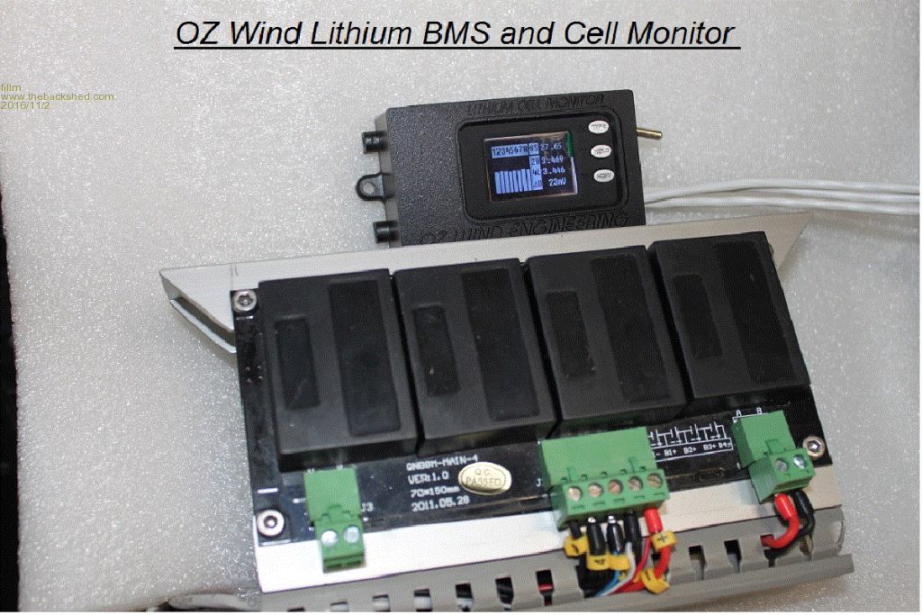 PhillM ...Oz Wind Engineering..Wind Turbine Kits 500W - 5000W ~ F&P Dual Kits ~ GOE222Blades- Voltage Control Parts ------- Tower kits |
||||
