
|
|
Forum Index : Electronics : a new way to balance lithium ion battery
| Author | Message | ||||
| Tinker Guru Joined: 07/11/2007 Location: AustraliaPosts: 1904 |
Thanks guys for explaining the 'junsi' thing. I have to agree with fillm that these things should not unbalance cells, too small, perhaps there is something else going on with busman's battery bank. That balancer fillm pictured above looks flashier than mine but then its a production unit compared to my endless prototype. My BMS has visual cell monitoring too, it used to have data logging as well with the 8 cell bank but this logging program won't cope with 16 cells I now have. My thoughts about audible/ visual OV/UV alarms, one has to be there to hear/ see them. I prefer OV/UV disconnect charge/ load, that saves the bank while absent from home and something goes wrong. Having said that it never happened so far with my LiPo bank, been away for up to 4 weeks and the system kept on running by itself. I do have provision for under cell Voltage load disconnect (turns inverter off) or over Voltage disconnect (isolates bank from the solar charger). Both would reset automatically. But at the moment they are not connected as I'm playing with a bigger inverter. I'll deal with these once my big inverter has run for a while with no problems. Klaus |
||||
fillm Guru Joined: 10/02/2007 Location: AustraliaPosts: 730 |
Hi Klaus , Bussman , All good and points taken and I have heard a little some time back with your bms an logging endeavors through a mutual friend. My take on the whole thing, you have to have quality equipment to look after the #1 substantial investment and is always the primary component to protect. Personally... I like Outback or Plasmatronics and you to then very accurately control the charge . From a basic PL20 you can easily control an almost infinite solar array as well as a turbine if need be, same goes for the Outback and probably the midnite.. along with a host more. So with a PL20 and some relays SSR or Old School Contacts is infinitely expandable and a Jusni is a low cost under $300 - $400 ,high quality charge control and monitor or logger solution for a lithium battery set .. and quality BMS systems are out there. ... Forget EV BMS systems for Off Grid or Hybrid. Yes correct , an audible alarm may seem pointless but it is something and the Junsi is extremely accurate, for a small cost and even smaller package ... how do they do it ?? with technology these days I am sure there is a friggin App that will alert a mobile from an output signal ... Must look into that . But if a cell gets 250mV out and and alarms for 15min while the BMS pulls it back, then its usually at the upper charge limit and the excess amps are backed of curbing voltage rise by the controller and its matching useage. I think all the hype and worry about lithium is overrated, they are the easiest of all batteries to use and charge , basicly charge is virtually max or min & off. No Gassing , stack anywhere and take up virtually no room . 20kW fits under my bench. Once set up with all the right gear and the LV protection there is virtually no need to look at it apart from looking at it, if you want some excitement, get a wind turbine, or build an inverter  But what most here may overlook is the fact that we or I " The Back Shed enthusiast/s" are the 000.001% of the real world stored and alternate energy systems doers and tinkerers, meaning no disrespect. Most people who live off grid just want the system to work and not to make work. They are at the mercy of systems ..ie inverters and charge controls that are programed to kill batteries at the expense of not turning a generator on and that can be self inflicted, then run to the deaths door of 10.5V. Then they think that smashing them with crazy 16V charge cycles will magically restore the LA battery to it former glory. From memory Klaus you to have an Outback as well as a Latronics inverter. Its nice to play with all the other toys and projects like we do but what do we really have behind the projects that controls and gives reliable power? Yep I'll plug the 3 I have mentioned as they just work day in day out for me, are quality commercial units that meet standards have correct algorithms and can be manually set and makers who thoroughly test their products, and from personal experience know some of the ones who do not step away from back up and good support if needed. If others want to go down their own paths it personal choice. Its great to broaden the knowledge base and understanding of where the smoke lives and I usually get crucified for my opinions that have changed from the early days. ..... But I am still here and try to help -- if I can and have time, I like to build stuff too. PhillM ...Oz Wind Engineering..Wind Turbine Kits 500W - 5000W ~ F&P Dual Kits ~ GOE222Blades- Voltage Control Parts ------- Tower kits |
||||
Downwind Guru Joined: 09/09/2009 Location: AustraliaPosts: 2333 |
William, Im confused with the Junsi drawing from 6 cells, thats 18v given you have 3v cells from my understanding. Should you mean 4 cells at 12v would make better sense. The Relativities unit works well when used as designed, but not in your setup as the Relativities unit is programmed to operate when the charge voltage exceeds a upper set voltage, not designed to work when the discharge voltage causes the unbalance. The problem is in your setup connections not the balancer used. From what i recall the Junsi uses V0 (ground) as reference to all cells, so if you added a simple voltage regulator to supply the 2 Junsi from the full 24v supply then you will have a equal drain across all the cells in the 24v pack and problem solved. Sometimes it just works |
||||
busman Newbie Joined: 30/10/2016 Location: AustraliaPosts: 21 |
Well that is the way the Junsi works, it only draws its power to operate from the first 6 cells.4 in the case of a 12 v system.But of course is connected to all 8 in a 24 v system I don't understand how a voltage regulator would work, surely if you want to measure cell voltage you need to be connected to the cell ? This is the first explanation of relativities I have heard, been impossible to get info so I put one on and hoped, now seems a waste of money ? And what is the voltage above which they are supposed to start working at ? Still learning...... William |
||||
| fillm Guru Joined: 10/02/2007 Location: AustraliaPosts: 730 |
Pete, I think the Relativities Balancers he has are the first version and there were problems with that version, the second version that works and you are using was never released after I sent Gordon the balancer I have and he tested it. I wont' expand any further than that. There are quite a few applications for the Junsi and it can be connected in a few different ways , Here is a good description and review with Specs .. Etc Junsi Review If William is using an NO relay for charge control , then the signal Volts from the Junsi can draw up to 500mA on the alarm output, this may be where the extra power consumption is as the running Screen & V measuring is only stated as 8mA. There is also a sleep function that can be used as well to cut power usage down. PhillM ...Oz Wind Engineering..Wind Turbine Kits 500W - 5000W ~ F&P Dual Kits ~ GOE222Blades- Voltage Control Parts ------- Tower kits |
||||
| busman Newbie Joined: 30/10/2016 Location: AustraliaPosts: 21 |
A few explanations here. Yes I am using a NO relay to do my control (cell over voltage) It draws 53 milliamps. The difference here I feel is that most of you guys are not able to charge at up to 120 amps @ 24 V, or even at 270 amps @ 24 v if I used the coach alternator. Nor do you have a central inverter/charger/control system that is data linked to it's satellites. When you are able to pour it in like this cell balance becomes an issue, looking at a Junsi bar graph at 100 amps coming in, lets just call the situation fluid. It is during extra fast recharging or discharging (up to 200 amps) that any imbalance becomes obvious, that is why, if you can have the cells as close as possible, you are able to exploit the full voltage range of the cells. This is what I have discovered over the last 2.5 years with our packs and systems. There is no extra problem with our systems, the reality is that if you gently recharge you will not see these problems, if you are aggressive with these batteries, you will. That is why I want better balancing, I want the maximum possible performance. |
||||
| Warpspeed Guru Joined: 09/08/2007 Location: AustraliaPosts: 4406 |
[quote]It is during extra fast recharging or discharging (up to 200 amps) that any imbalance becomes obvious[/quote] Now that is a particularly interesting observation. I am still looking at ways and means of home building a future battery monitoring system, purely as a mental exercise at this point. Too many other projects going right now to begin, just collecting and tossing around ideas at this stage... It would be nice to have a large screen bar graph of individual cell voltages, where all the individual cell voltages should line up horizontally, with millivolt resolution. It might also be a lot more revealing to also record the peak maximum and minimum cell voltages reached for each individual cell on the same display, as well as just display the current cell voltages. The ideal display would be something I could just glance at occasionally without really having to think much about numbers, something that will instantly show up any individual cell that is beginning to become markedly "different". Cheers, ĀTony. |
||||
| busman Newbie Joined: 30/10/2016 Location: AustraliaPosts: 21 |
Tony, that is one advantage of the the Junsi, there are 4 or 5 different configurations that you can set up to look at cell voltages, I find by far the easiest is the bar graph, others use different ones. If you use the logger version you can generate a LOGVIEW file for downloading to your comp to see individual cell performance over a period of time (whatever you set it to log at) And you get all this functionallity for around 30 AUD ! The only part you have to be careful with is the alarm port, do not exceed the 1/2 amp or the tranny in there will die, apart from that pretty strong It is really interesting to watch the bar graph during fast charging the cells are bouncing up and down like no ones business, they settle down as soon as you stop. I do not bother to dim my junsis I suppose if I did that I might be able to minimise this problem but I want them viewable whenever I feel the need to look at them William |
||||
| Warpspeed Guru Joined: 09/08/2007 Location: AustraliaPosts: 4406 |
It was the Junsi bar graph that originally gave me the idea. But I want my bar graph to be man sized, not mouse sized, and in brilliant colour that can monitor up to thirty cells. My entire system is built from highly original home made electronics, all of it. Part of the fun of the whole solar project is I can do it any way I want without any real constraints. Cheers, ĀTony. |
||||
| Tinker Guru Joined: 07/11/2007 Location: AustraliaPosts: 1904 |
At the above quoted price these junsi loggers do sound interesting enough to try them myself. But before ordering I have a question: Each unit monitors 8 cells. I have 16 cells (48V system). Can I use one Junsi for the first 8 cells and another for the next 8 cells? I'm not interested in alarms, just the graph feature. Klaus |
||||
| Warpspeed Guru Joined: 09/08/2007 Location: AustraliaPosts: 4406 |
In a word yes. Cheers, ĀTony. |
||||
| busman Newbie Joined: 30/10/2016 Location: AustraliaPosts: 21 |
From Hobbyking or progressive RC |
||||
| fillm Guru Joined: 10/02/2007 Location: AustraliaPosts: 730 |
In a few more words, Yes you can, the #8 cell becomes the end of the 1st Junsi Neg and the Pos Start of the 2nd Junsi. If you are going to data log then unless you have an isolated USB adapter for the second Junsi it will be a direct short and you will smoke your computer in there somewhere. PhillM ...Oz Wind Engineering..Wind Turbine Kits 500W - 5000W ~ F&P Dual Kits ~ GOE222Blades- Voltage Control Parts ------- Tower kits |
||||
| busman Newbie Joined: 30/10/2016 Location: AustraliaPosts: 21 |
Well I have added a couple of chargers from ozwind to my banks and am happy with the result. 12 v system was never much of an issue, sometimes with fast charging there was a bit of drift but not usually much of a problem with the Junsi loggers pulling equal power from all cells. However they only take from the first 6 cells in a 24 v system so compounding imbalances do occur around the end of the charging cycle. I have never seen my 24 v bank (800 ah) in single figures but after doing some memory and capacity checking I left the balancer connected overnight, with everything, including the 2 Junsi disconnected from the bank. Next morning the difference was 6 mv. This is a great result, when quick charging (from solar over 100 amps, from mains 140 amps), then starting from a virtually nil difference sees the gap at the end of charging much smaller, typically about 120 mv, which the balancer brings back over the next couple of hours. Normal running with both Junsi connected means a diff of 21-22 mv is achieved. These things are game changers, no longer is cell imbalance an issue With these things now available I will be replacing all the farm equipment batteries, and the electric golf carts we use with liths as the LA's die. |
||||
| fillm Guru Joined: 10/02/2007 Location: AustraliaPosts: 730 |
Hi William, I think you mean " Couple of Balancers " in the top line not chargers, thanks for your evaluation. Being able to balance a large 800Ahr 24V bank to within 20mV especially when I think your bank is made up of 8 x 100A/hr in parallel / series so 64 cells is making them work there buts off and sounds like they are doing the job perfectly. I know with smaller 400Ahr and 200Ahr they easily keep the differential in spec @ 10mV cell differential . And on smaller 200s they balance very quick. PhillM ...Oz Wind Engineering..Wind Turbine Kits 500W - 5000W ~ F&P Dual Kits ~ GOE222Blades- Voltage Control Parts ------- Tower kits |
||||
| busman Newbie Joined: 30/10/2016 Location: AustraliaPosts: 21 |
Ooops, must bin late at night ? Yes balancers, doing good job on my 64 100 ah cells. If you read the post, without Junsi 6 mv, so it is easily seen that having to rebalance the uneven draw of 2 Junsi has an effect, but still 20 odd is good enough for me, the thing with these balancers is that they are working all the time, not letting the imbalance compound. |
||||
| Warpspeed Guru Joined: 09/08/2007 Location: AustraliaPosts: 4406 |
Now all this has had me ruminating and pondering for quite some time. The unquestioned genius of Klaus is to blame for all of that. I have now come up with a few assorted ideas that might be of general interest. The first thing is how to connect up relays for cell monitoring/balancing in a fool proof way that cannot short out cells or misbehave, even if something goes desperately wrong with the relay sequencing. So here is what I came up with: 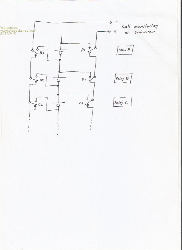 It uses one double pole relay per cell to connect each cell across the output as required. But there are no constraints in relay operation. No need to release one relay before operating another. In fact even more than one rely operates or fails to release, nothing really terrible can happen. Next problem for individual cell voltage measurement requires a fully floating voltmeter. For accurate cell balance measurements the SAME voltmeter is really required so very small millivolt differences can be compared without introducing cumulative errors. The best thing for that might be the "flying capacitor" method of voltage isolation. The concept is to switch a capacitor directly across each battery cell so it charges to the exact cell voltage. Then disconnect it from the cell and connect it directly to a ground referenced voltmeter. By switching back and forth both capacitors rapidly assume full cell voltage with minimal error. Relay contacts could in theory be used to do this, but a much nicer solution, that is not going to mechanically fall apart would be some fully isolated optically driven fet switches. 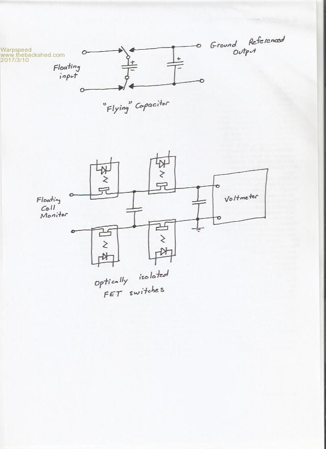 The switching devices could be International Rectifier PVA33N. http://www.irf.com/product-info/datasheets/data/pva33.pdf These have 300v isolation when off, can carry 130mA when on, and have a resistance of less than 25 ohms when on. That is enough current rating and resistance to ensure no blow ups even under worst case conditions with the largest capacitors and cell voltage differences. Switched at about 100 Hz (with non overlapping clocks) that should work well for both cell voltage monitoring, and I might even get a bit of "Klaus" full time cell equalisation for free thrown in, if my capacitors are made suitably large. So my ground referenced voltmeter can monitor individual cell voltages with up to a 300v battery anywhere between 0v and +5v, and read every cell the same without requiring troublesome very carefully matched resistor networks or op amps. By setting the A to D converter ref Lo and ref Hi voltages at say +3.0v and +3.6v I can fill the screen vertically with 256 bits over any desired voltage span up to +5v. That is about 2.3mV resolution which should be enough to clearly see any cell differences. That would make a nice front end for a data logger or battery monitoring system, and its really simple. The next thing I did was build in hardware a prototype VGA video generator that scans a 1K x 8 dual port ram and puts up a picture on an LCD computer monitor. I know any PC or lap top can easily do that, but not with only one watt of power. If I use a PC to monitor my battery, it would just about double my night time power consumption, which would be a giant step backwards. I used a low end microcontroller with A to d converter to link the flying capacitor system to my video ram, and it displays the voltage of up to 30 cells at the moment, plus a peak hold that shows the maximum and minimum voltage excursions reached, with real time cell voltages in between. Sort of like a big wide screen screen "Cell Log" but with more channels and peak hold. Its not finished yet. The video and microcontroller part is all working. And with a potentiometer I can move the display voltages around on the screen and see the peak max and min voltage holds work. On screen graticule lines at 100mV intervals give a pretty good indication of voltage. Plan to fit undervoltage and overvoltage alarms for every cell, and battery disconnect signals, but have not done that at this stage. Its just software... Still don't have any relays hooked up or the flying capacitor system built. I don't even have a Lithium battery yet to monitor. Early days yet. But I want to get all this going before I actually get the battery. My camera is FUBAR right now, and must buy another one with a good macro lens. So no pictures yet unfortunately. Just though I would bring everyone up to date on my latest adventures. Cheers, ĀTony. |
||||
| Tinker Guru Joined: 07/11/2007 Location: AustraliaPosts: 1904 |
Tony, I'll take my hat off for coming up with your clever relay switching arrangement in that first sketch. You have no idea how stupid I feel now  , not having come up with this myself. , not having come up with this myself.My excuse is, having started up with super capacitors to do the balancing, there were no reasonably priced relays available with that contact arrangement *and* a high current rating, as the inrush from these caps is quite big. All I could find for an affordable price (remember, there are lots of relays involved) were automotive type relays and these do not have changeover contacts. The relays also had to be physically small to fit so many on a reasonable sized PCB. Automotive relays were OK for the 24v battery bank but failed miserably with the 48V bank after I upgraded my system. Now I'm using DPST relays with software control to prevent the wrong ones operating (which instantly blows fuses BTW  ). ).These relays are small enough and with a sufficient voltage rating but have only 2A max current rating. As it is, they usually switch <0.5A while equalising from my isolated voltage source, set to 3.8V. The system is now trouble free, it just gently clicks along after the battery bank reached the end of the absorbing state - the solar panel voltage reaching >80V wakes the equalising sequence up. Each of the 16 relays only comes on once in each minute. With an operating life of a quoted 10 million mechanical cycles they should be good for a few years yet. I do only visual monitoring of the cells now, during the equalising cycle a small DPM and a display of the cell # lets me know what's going on. These lithium cells are so closely matched (within <5mV each)while there is no charging happening, any logging is only useful while the batteries are charging. Sadly, the picaxe based logger I have only does 8 cells and its resolution was not that good anyway. Klaus |
||||
| Warpspeed Guru Joined: 09/08/2007 Location: AustraliaPosts: 4406 |
Klaus, I have been thinking about this relay problem for quite a long time, and it was something I came up with only after looking at many other ways to go about it, all of which had many possible failure modes that I did not much like. As you say, the relays will be pretty expensive as we need many for something like this. I have ordered eight of those cheap Chinese relay boards from e-bay to try initially. They only have single pole relays unfortunately, so I need to run two eight relay boards to monitor just eight cells. Its not a good solution, but its a low cost way to get started with a working prototype. Doing it this way opens up a few problems. If one board stops working we are in trouble. Much better to use dual changeover contacts on the one relay, that way nothing destructive is really possible. Your ultracapacitor cell balance idea is still a winner, and I had thought of placing an inductor in series with the ultracapacitor. That will limit the initial current inrush, the LC circuit will then ring at very low frequency with a decaying amplitude. When the relay contacts for that cell finally open, there should be no stored inductive energy remaining. It should be very gentle on the relay contacts. I still think your cell balancing idea can be combined with individual cell monitoring. If we switch to a different cell, there will be an initial energy interchange, but after a few seconds the capacitor voltage should settle at the actual steady cell voltage. We can then read that cell voltage off, just before we switch our next relay to the next cell. If the relays sit on a particular cell for several seconds we should be able to both shuffle some useful energy around for cell balance, AND do some cell voltage monitoring with the same system. If it all runs continuously, we may only need a fairly small balance capacitor. I have absolutely no idea what the requirements are, but it may need very little to stay in excellent balance over very long periods. Cheers, ĀTony. |
||||
| busman Newbie Joined: 30/10/2016 Location: AustraliaPosts: 21 |
I do understand how you guys like to tinker and come up with solutions for problems, but to me the above is re-inventing the wheel a bit. Balance of our 800 Ah 24 V pack in our motorhome was always a real PIA as we had constant minor draw from the first 6 cells only. Enough to wonder if going LiFePo4 was worth it However since fitting the Ozwind balancers that is all in the past and we could not be happier. I wonder if all the effort/testing/changes/hair pulling on inventing something that already exists, at an acceptable price, is worth it ? |
||||
