
|
|
Forum Index : Solar : HWC element powered from HV PV array
| Page 1 of 6 |
|||||
| Author | Message | ||||
| Solar Mike Guru Joined: 08/02/2015 Location: New ZealandPosts: 1204 |
Moved this design to a new topic for discussion. The original question was could something be cobbled together from off the shelf components to power a 16R 3.6 Kw hot water element from a high voltage PV array, comprising 8 PV panels each with a Vmp of 30 volts and current 8.5 amps or so. Perhaps for low power\voltage with a 50v element, but nothing otherwise readily available, so we have to design it. The HWC element can draw max of 15 amps @240 volts, the 8 pv panels above, output 240v, but don't have the current capacity to drive the element without collapsing the array voltage. Warp has done some valuable measurements at various loads on a PV panel to prove there is a broad enough power output peak from the panel to allow a simple voltage switch to charge up a capacitor bank to the Vmp voltage and discharge using one or more mosfets into the element resistance, as the bank voltage drops to a lower threshold point, the switch is opened, allowing the bank to recharge. The process repeats at a rate determined by the size of the capacitor storage and the energy from the PV, with approx 10,000uf the frequency is around 50-100 Hz, there is a dead time in the process as the bank recharges, this suggests that this MAY provide enough off time to stop any arcs created when a thermostat opens; Note this has not been tested, so proceed at your own risk here. This process can be used on bigger arrays, however there reaches a point where the PV output is greater than demand from the element, where the switch will always remain on and have no dead time to stop contact destroying arcs forming on the thermostat contacts when they open. To allow more dead time the series PV voltage can be raised eg 10 series panels Vmp approx 330v (high power panels typ 33-36vmp); the higher voltage will allow higher current pulses into the element thus extending recharge dead time. Dangerous scary voltages, so proceed at your own risk here. This first part of the circuit shows the capacitor bank and the mosfets, I have allowed for 1-3 parallel mosfets here, the one specified is very cheap on AliExpress and no doubt a clone, however 3 may work ok, will see... but you want < 50mR resistance to keep losses to a minimum. The 0.002R source resistor is to allow a current sense for display on a LCD screen along with power etc should you want to add a CPU to the mix. The 12v power to run everything is one of those cheap 230ac to 12v 5 watt switching PSU's, it will run OK from the high voltage DC. Note the 0v line is connected to the high voltage DC, so keep everything well insulated behind perspex etc. It is possible to completely isolate the low power driver and control from the HV, but will make the design more complex. 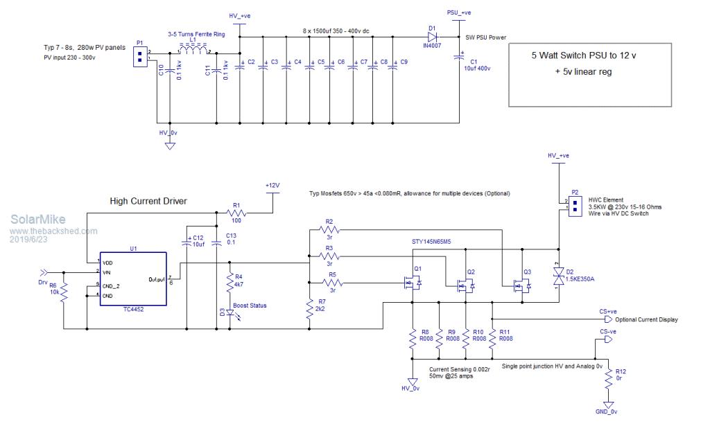 Controller side has a rail/rail op amp acting as a comparator and RS flip flop to allow independent setting of high\low capacitor bank voltage switch points, place them 10 volts or so apart to start with. Optionally not absolutely necessary is a heat sink sensor to turn on a small 12 volt fan for cooling and a hot water temperature sensor to disable the power into the element, I would suggest this be set lower than the fitted mechanical thermostat in the HWC, this adds some redundancy to the circuit should a thermostat fail with perhaps disastrous consequences. Sensors used are the MCP9701T TO92, they are a linear thermistor with a buffer stage, may be tricky to properly insulate them. 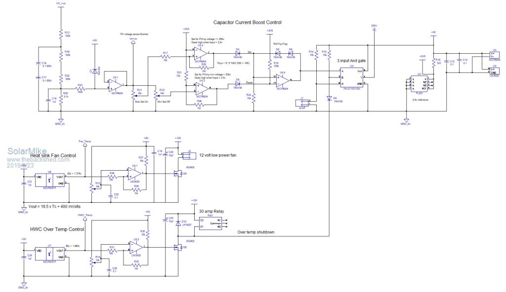 Cheers Mike |
||||
plover Guru Joined: 18/04/2013 Location: AustraliaPosts: 306 |
I am rather interested in studying this a bit closer, as it seems I can use this for a Max 6KW heatbank system with two elements. Presently only run on one element 240V Mains but it seems there is merit in installing the second element again but driving this with solar panels. I am also eying off my hot water system running on a 500W element at the moment (accidental as it should be 1500W but was not available when I needed it then forgot to about the smaller element for a number of years and just discovered) The capacitor-boost schematic is very fuzzy on my pc and even the picture itself when I try to magnify is a bit hard on my old eyes. Any chance your system can produce a pdf version, that normally overcome resolution problems. |
||||
| Solar Mike Guru Joined: 08/02/2015 Location: New ZealandPosts: 1204 |
No problem 2019-06-24_065938_HWC_Schematic.pdf I have ordered some of the items for this, soon as they arrive will start on a pcb design; will post the gerbers here. Currently renovating a house, have just replaced all the old plastic plumbing pipe work and installing a new 300 litre solar ready stainless steel HWC. The HWC has dual 3KW elements, so will power the upper from mains 230vac with a timer and the bottom one from this circuit and an array of 10 x 300w PV panels. Decided to not install solar heating panels even though the cylinder has the extra fitting ports, it works out less expensive to use PV panels now than purchase solar heating ones, pv has many advantages in that no worries about frost, pumps wearing out and leaking. Will have to get code sign off and electrical inspection on this project, which maybe an issue as I doubt any electrical inspectors have come across this before. Cheers Mike |
||||
| Davo99 Guru Joined: 03/06/2019 Location: AustraliaPosts: 1585 |
Would you be interested in making some of these boards to sell Mike? |
||||
| Solar Mike Guru Joined: 08/02/2015 Location: New ZealandPosts: 1204 |
I will be posting the gerbers, anyone can get them made, guess problem being there is a minimum quantity per order from likes of JLPBC of 5. Postage usually costs about same as the order, so may not be cost effective for me to sell them. Will see once its been sorted and running. Mike |
||||
| Davo99 Guru Joined: 03/06/2019 Location: AustraliaPosts: 1585 |
I'd Like a ready to go board and I think other people would too. If it were OK with you and was practical, I'd be interested in throwing some $$ into having them manufactured and selling the things. I believe there would be a market for something like this where it is a matter of wiring rather than building. There is a unit being sold now which seems overly expensive for what it is and of questionable reliability. With the availability of used panels getting easier and cheaper, I think a dedicated PV water heating controller would have sufficient appeal to make it a worthwhile Product. Anyone know of any Companies that would do a limited run of these things? |
||||
LadyN Guru Joined: 26/01/2019 Location: United StatesPosts: 408 |
I think the exact route Mike proposed at the beginning - have the PCBs openly available so that anyone can order them and populate with parts is the best way forward. Do you have a few links? Is it that Techluck product? Since I know nothing about the money side of things, I showed this thread to one of my mentors who's a mechanical enginner turned intellectual property attorney and she pointed out that the weight of liability shifts significantly depending on whether a kit was sold as parts or as plug n play. Plug n play requires certifications, accredations and other ations that kits just don't require or at least the weight shifts on to the assembler. Actually, we had been having this discussion for a while on this topic because I found some solar inverters meant for DIY installation that were potted and completely inaccessible for reuse. Since I was interested in these as a source of toroids, I was very upset and spoke with all my mentors to find out what I should do next and this point came up. The potting is barely for environmental protection - a good gasket ata fraction of the price would be a sufficient seal - but actually more to dissuade modifications or rework. The potting itself is not cheap - heatsinking has to be rethought, increasing costs. Weight goes up tremendously, also increasing costs, and there is no salvage value at all, also increasing costs. Yet the company does it to reduce their liability and to make any modifications or rework easily noticable in case of a dispute. It's a one and done deal. One single component dies and you have to buy the whole thing again or shift the whole liability on your shoulders. Now, these boards, to be of any good use need to be high voltage and due to their nature, capable of hundreds of amps of surge current. Yes, it can stop a heart in a heartbeat and when that happens, fingerpointing will take place. I could have made thousands of dollars in profit and then it's all gone with one single incident - with the burden of a life and a family on my hands. I have been reading that some Chinese companies have been copying inverter design and code from here. At first I was extremely upset about this. It did not seem fair. I reached out to one of my mentors who's a web developer to ask if he could set up a forum where we could invite select people so everyone is known. He was willing to do all the work but asked me the purpose and gave me a few homework items. Due to that I looked at how much widespread the use of good value inverters has become vs. the extremely expensive ones that were the norm even a few years ago and I saw a silver lining. It still does not seem fair but I would rather have 1000 people live a happy life than 10. So while I personally still won't purchase any of the inverters that are known to have copied designs from here, I am happy copies are being made and more people are living a happy life because of it. The reason why Chinese stuff is so cheap is because their costs are extremely low! I have come to realize that design and parts costs are a fraction of the overall cost of a high volume product. Insurance, maintainance and customer support eats up majority of the costs. Insurance - for the Chinese - when things go wrong, someone dies or a house burns down, fingerpointing does not end up doing a lot of damage becuase the end user and the manufacturer or reseller are continents apart. Even if someone spends enough money to track the company down and litigate, the Chinese just shut shop at "MakeSkyRed Solar Inc" and open a "MakeSkyPurple Solar Inc". Also, we have not even considered the intellectual property side of things - even if Mike, Tony was to hand over the whole intellectual property rights of this project to a company, for free, it's still on that company to ensure this is not encumbered by a patent or similar. Mike, Tony designed this from the first principles but that does not mean this is the first time this has been thought about. It could already be tucked inside a patent somewhere. For example, the Techluck website mentions patent pending - I don't know what the patent is and whether I can read it - but if that product is conceptually similar, there could be some grounds for discomfortable back and forth. All of this is less of an issue in China but probably really does not work in developed countries where the owner is held at a much higher standard. Last of all, I dont think we have discussed the complexity of logistics and shipping/insurance costs invovled - I was personally exposed to this nightmare trying to purchase toroids and it has severely discouraged me from getting involved in anything that includes shipping any product whatsoever in my life. After thinking about all of this: 1. I think the Techluck person might be a good liason in this initiative. He has sold a few units and knows what the market is like. He knows what's involved and is familiar with the details we are surely missing 2. How much of his retail price is overhead vs profit? I won't be surprised if he's paying as much to ship his product as the BOM cost 3. If his BOM cost is higher than this design, or this design is more featureful, he might very well swap his design and get us real life feedback on what works with this design and what does not 4. What volume and quality of of customer support calls does he get? HOW does he handle situations where the buyer is obviously not qualified at all to use the product and would take a huge amount of time to train and set up? I would have got in touch with him rightaway if I were an adult, but no adult takes me seriously and I have completely given up on that because the whole process exhausts me. Apparently being older than 18 gives a person superpowers that I don't possess yet. My speech impediment does not help either. I have been hung up on as a prank caller more times than I can count. I can type fast and that works for me. For this project to reach volume, it might actually make sense to go the exact route Mike proposed at the beginning - have the PCBs openly available so that anyone can order them and populate with parts. Someone dies or the tank blows up - well, neither Mike, Tony or any one of us is to blame. Then we make Youtube videos or a picture guide showing how to populate the board with parts - I am as untrained as one can be and if I can build a board from scratch, anyone on Youtube can! This might entice the Chinese to clone this project and make it available at volume at a fraction of the price as usual - all populated and ready for plug and play incl. free shipping! I have tried to put in time and effort in this reply because I deeply care about everyone here and wanted to think of any way harm might come upon you. I would like to hear all your thoughts on this - I completely lack any practical experience in these matters and it might very well be things in real life is way different and less complicated - I like to learn. |
||||
| johnmc Senior Member Joined: 21/01/2011 Location: AustraliaPosts: 282 |
Good Day LadyN, Thanks for the effort required , in presenting the problems you have outlined. I do not know the answers. cheers john johnmc |
||||
| Warpspeed Guru Joined: 09/08/2007 Location: AustraliaPosts: 4406 |
Most of us here are retired old guys with the dual interests of solar and electronics. I think many of us are glad to finally be out of the commercial rat race, and are just interested in exploring new ideas and helping others and passing on some life experience. There is some evidence to suggest that the Chinese read our Forum and many of the ideas and improvements we come up with find their way into commercial products. And good luck to the Chinese ! The problem in the West is the much higher cost of parts and labor, crippling government regulation, legal obstacles, corporate thuggery. We can never compete with China on a cost basis. Its much better if we can just come up with the ideas, and the Chinese produce the item, and we can buy it and use it at less cost than we could possibly ever build it for ourselves at home. This whole solar hot water concept appears to be technically very sound and quite practical. The next step will be for a few different people to build and test prototypes, and come up with some innovative ideas about how to improve or simplify the physical construction. When the beaten path becomes very clear, and there is a growing interest, only then will the commercial guys step into it. The demand has to be there first. Cheers, �Tony. |
||||
| LadyN Guru Joined: 26/01/2019 Location: United StatesPosts: 408 |
Your response highlights the difference between a rank newbie like myself and a master practitioner like yourself. I wrote 20 pages worth of words and you, in a few sentences, conveyed more than I ever could! i love this forum and the people in it. I am very sure there's a demand for this system - but it has to speak to commoners like my brothers, my neighbors. You and Mike are well on your way to design the core but we are far from done. We have to come up with a formula to figure out the capacitor bank size to the tank capacity and expected heating/recovery time and present those in a table for people to pick and choose. Yes, there are a lot of unknowns involved to get a good estimate, so we can use some madeup numbers (200Vmpp, 10A Isc, 10x 2700uF 200V bank, 2.4kW 120V elements) for our computations in examples. |
||||
| Warpspeed Guru Joined: 09/08/2007 Location: AustraliaPosts: 4406 |
It should not be too difficult. There are only two major mains voltages used around the world, 110-115v and 220-230v. Heating element wattage will vary, but it may be possible to order specific sizes to suit the solar capacity. Solar panels seem to have standardized around 24v nominal, so there are only likely to be groups of four 24v panels in series for 110-115v, and eight 24v panels in series for 220-230v. The main difference will be in the electrolytic storage capacitors. We can store four times as much energy (per microfarad) at the higher voltage, so that becomes a lot more cost effective and efficient. I very much doubt that the actual capacitor value is all that critical within very wide limits. It only determines how fast the system cycles on and off, not the amount of energy transferred over time. Cheers, �Tony. |
||||
mackoffgrid Guru Joined: 13/03/2017 Location: AustraliaPosts: 460 |
I haven't read this whole thread but in case it's pertinent, You can order Hot Water elements to suit. I actually got a price off Romar Elements to have a 240Vac 2400W element and a low voltage DC element 600W in the one unit. It costs more because its bespoke. A little over $100. |
||||
| Solar Mike Guru Joined: 08/02/2015 Location: New ZealandPosts: 1204 |
Good feedback, further Ideas welcome. I agree, until a prototype has been built and tested it is to premature to be suggesting commercial spin offs. The circuit suggested in reality is too dangerous for any commercial design or construction by paint by number makers. The control section should be completely isolated from the high voltage area, 300-400 volts DC can kill you in an instant and it only takes a lapse in concentration to make a perhaps fatal mistake. In that regard the current design requires some serious work to make it safer for the masses, I have some ideas for that and will investigate. If anyone wants to build it on vero board or similar it will still work well at lower voltages, eg 50 vdc, but I will not be producing any PCBS for the current circuit. Anyone running such a device would want to know, what is the current hot water temperature, how much power is it putting out, will the cylinder be hot by the end of the day, do I need to switch on the main AC element. So I think there needs at least a minimal LCD display for user interaction etc. Cheers Mike |
||||
| Davo99 Guru Joined: 03/06/2019 Location: AustraliaPosts: 1585 |
I think this has answered my question in that NO, there isn'a way to put together pre built components with a few extras to make this work... Unless one does a battery/ inverter setup to power the element through a PWM Controller. I think there is getting a bit of pedantic over zealous safety mentality creeping in the discussion here. There are all sorts of inverter boards as widely used here amoungst other things available on fleabay. The guts of what must be stun guns leaps to mind which could easily be lethal. If someone BBQ's themselves with some component, Tough titties. I don't see how the seller can be responsible and to suggest they would be to me smacks of Protecting the deserved from the process of natural selection. Perhaps my term of Plug and play was wrong. Perhaps something like "wire up and add a few components" may have been more accurate. I think the teckluck product falls into that category. Uf you are an imbecile and kill yourself wiring it up, for me, bad luck. Eitehr have the competence to DIY it or get someone it than has the required skills. As upsetting as it may be to some, I do not pander to protecting idiots from themselves. I can't see why a board with all the components on it cannot be be sold same as these other inverter boards where they have to be wired up and a cap bank fitted... as a suggestion... for their potential use. My idea was to keep things simple that those with some electrical and DIY skills could get a bunch of parts to make this work. Clearly the answer is that is not possible. What we seem to be coming back to, and I thank sincerely those that have taken the time to look at this and design something, is something that only those with significant electronic skills can own and use. If it can't be made available as a product people such as myself can wire up or have wired up, then this misses the mark of -My- idea. Not saying it may not be of benefit and highly useful, just that it misses the target market -I - had in mind. I talk on Forums with people that make their own or wire/ re wire generators and off grid systems and these are the people I had in mind. While capable of being able to wire things up with their electrical skills, they are not competent with electronics which is another ( higher) skill set in my mind. I guess those people like me will have to stick to either low voltage elements or wireing up panels in series/ Parallel with enough grunt to drive the elements directly. Still seems to an ignorant like me that it should be possible to cobble something together with out high level electronic skills even if it were using an arduino which again is something with many mains voltage projects are available for. I'll watch with great interest however how this pans out. Maybe one day there will be something in a component form that will be able to be used for the job! :0) |
||||
| LadyN Guru Joined: 26/01/2019 Location: United StatesPosts: 408 |
https://www.thebackshed.com/forum/forum_posts.asp?TID=11493&TPN=2 Mike, I think the path you took with a working schematic is just perfect. As you know, I make pocket money programming firmware for small businesses and the time they spend behind PCB rework and enclosures to meet certification etc is absolutely insane. I would rather learn about the next inverter or another project from you than have you spend an inordinate amount of time making a legally defensible PCB when someone kills themselves and the lawyers sends you a letter. Let people build their own PCBs any way they like. Yes, I will be making a verboard version of this circuit, but using a ESP32 dual core with a wifi/websocket endpoint instead of LCD because I just can't see well. You sound exactly like everyone I know, but I live in a farm. Our neighbor got bit by a rattlesnake on our property and we did not get sued. That's just how it works where we live. we cant afford liability or whatever insurance and never had to use it. Where I go to school, in the city, the mentality is absolutely different. Everyone carries liability or whatever insurance. If I throw up at your house and then slip on it, you pay for everything. This really happened! No one even blinks about it. A distracted parent drove right into a wall at school because they took a route that had red "DO NOT ENTER! WRONG WAY!" signs on them by the entrance and yet they won their lawsuit against the school because the signs were "not visible enough". Those signs had been up ever since I remember. If you look at the glasses I wear, you could mistake them for a bulletproof defense mechanism and even I can see them. The school provided footage of the parent looking at their PHONES WHILE DRIVING INTO THE WALL and that took something like 5% off their liability and they were required to pay only 6 months worth of pay to the now disabled parent who cannot go to work now anymore. Plus they will get paid by the state for their disability too. It's now a person's full time job to just stand there during school drop off and pick up time. .. and my dad who's a veteran had problems paying for the electricity we use because VA funding is not being met because the state has other obligations. I would really like to visit these places and learn what people are doing! :) I won't be that disappointed. Maybe you google a specific phrase in a few months that lead you to a JLPCB link that you just hit order and that also happens to have a blog link that shows you how to wire it up! Of course, you have to run it by a plumber, home inspector and relevant city, county officials even before you start it up and then have a licensed electrician hook it in! |
||||
| Solar Mike Guru Joined: 08/02/2015 Location: New ZealandPosts: 1204 |
Don't be too despondent Davo99, as I said I will modify this circuit to make it safer to construct, all I have to do is provide an isolated sensing of the High voltages and run the control section from an isolated supply, then drive the mosfets via opto-couplers. This will add some additional complexity to the design, but more importantly make it easier and safer to work on. I think a CPU output section could be an optional extra and easier to do if it wasn't sitting at 300 vdc potential. I want to build one of these also for the house that's being renovated, my intention is to use 10 series 280 watt 33Vmpt volt panels that I have sitting in the shed, unloaded they are nearer 40 volts, have already purchased 10 x EPCOS 1500uf 450v caps for the project. More to come... Cheers Mike |
||||
| LadyN Guru Joined: 26/01/2019 Location: United StatesPosts: 408 |
Mike, what's the average price for this set excl. S&H |
||||
| LadyN Guru Joined: 26/01/2019 Location: United StatesPosts: 408 |
Mike, in your experience, what's the typical price for this set excl. S&H |
||||
| Solar Mike Guru Joined: 08/02/2015 Location: New ZealandPosts: 1204 |
Picked them up second hand $15 each, came out of old inverter psu's, brand new $40-50 each On Ebay you can get these 4700uf 450v , US$26 each, quality unknown, prob need two. Cheers Mike |
||||
| Davo99 Guru Joined: 03/06/2019 Location: AustraliaPosts: 1585 |
Just to note Mike, I was not complaining, it is as it is. If it can't be done the way I'd like, well that's it. If it can with a workaround, then that would be fantastic. I appreciate the effort you ( and others) are putting into this and the fact you are making the info freely available without making people whom would be interested in it jump through hoops. I very much look forward to seeing what you come up with. Thanks again for your efforts with this and your generosity in allowing others the benefit of your skills and experience. |
||||
| Page 1 of 6 |
|||||
| The Back Shed's forum code is written, and hosted, in Australia. | © JAQ Software 2026 |
