
|
|
Forum Index : Microcontroller and PC projects : Colour Maximite 1.5? or something
| Page 1 of 13 |
|||||
| Author | Message | ||||
| matherp Guru Joined: 11/12/2012 Location: United KingdomPosts: 11540 |
Please find attached a version of the PicoMiteVGA with USB keyboard support. PicoMiteVGA.zip Flash the firmware as usual Connect a USB keyboard to the Pico USB connector using a suitable adapter Power the Pico with 5V on the VBus pin (pin 40) You can connect a USB-TTL converter as a console to pins 11 and 12 of the Pico (GP8=TX and GP9=RX) 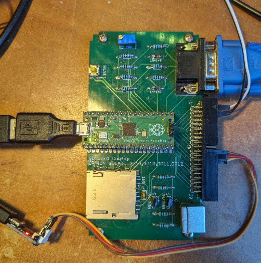 The firmware will start as usual and assuming the connections are good will announce that the keyboard is connected. Connection works for me through a USB hub but the TinyUSB software may not support all variants 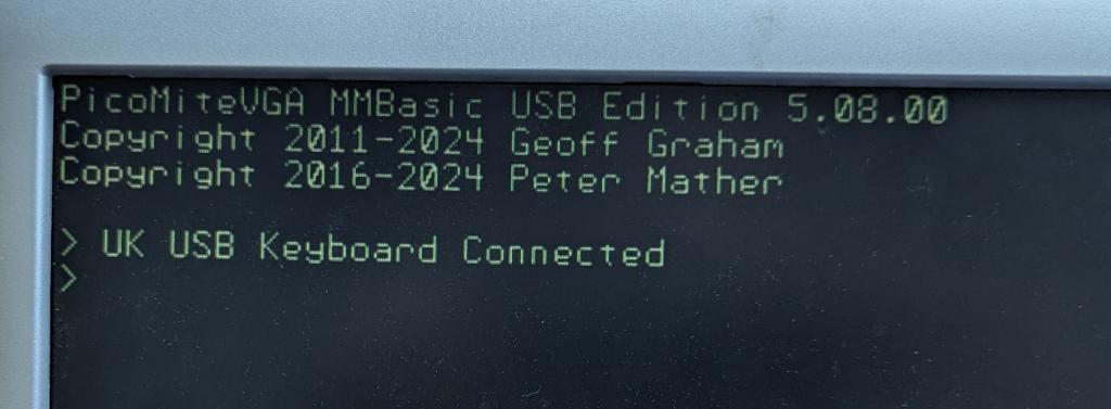 From there the firmware is pretty much identical to the standard PicoMiteVGA except for: UPDATE FIRMWARE command is not available so use the boot button PS2 functionality is completely gone as is support for the mini I2C keyboard Supported keyboards (OPTION KEYBOARD code) US (default) UK DE FR ES BE Others can be added a a later date given support from the relevant language users Use OPTION KEYBOARD REPEAT firstmSec, sunsequentmSec to set the repeat rate (default 600, 150) New Function: KEYDOWN(n) Returns the decimal ASCII value of the USB keyboard key that is currently held down or zero if no key is down. The decimal values for the function and arrow keys are listed in Appendix F. This function will report multiple simultaneous key presses and the parameter 'n' is the number of the keypress to report. KEYDOWN(0) will return the number of keys being pressed For example, if "c", "g" and "p" are pressed simultaneously KEYDOWN(0) will return 3, KEYDOWN(1) will return 99, KEYDOWN(2) will return 103, etc. The keys do not need to be pressed simultaneously and will report in the order pressed. Taking a finger off a key will promote the next key pressed to #1. The first key ('n' = 1) is entered in they keyboard buffer (accessible using INKEY$) while keys 2 to 6 can only be accessed via this function. Using this function will clear the console input buffer. KEYDOWN(7) will give any modifier keys that are pressed. These keys do not add to the count in keydown(0) The return value is a bitmask as follows: lalt ? 1, lctrl ? 2, lgui ? 4, lshift ? 8, ralt ? 16, rctrl ? 32, rgui ? 64, rshift ? 128 KEYDOWN(8) will give the current status of the lock keys. These keys do not add to the count in keydown(0) The return value is a bitmask as follows: caps_lock ? 1, num_lock ? 2, scroll_lock ? 4 Note that some keyboards will limit the number of active keys that they can report. I intend to do a SMD design for this with an onboard USB-C for power and connection to the serial console via a CH340, with RTC, Amplifier based on a modified version of this.  Edited 2024-01-27 00:59 by matherp |
||||
| robert.rozee Guru Joined: 31/12/2012 Location: New ZealandPosts: 2530 |
hi Peter, before rushing ahead with a PCB, you may want to look at adding a couple or three USB-A sockets along with an onboard USB hub (BigMik and I, along with others, tested several single-chip solutions). short pogo pins can be used to connect from the DP and DM pads under the pico to the hub chip. with an onboard USB hub and the USB-A sockets, the user can then connect keyboard, mouse, and a second pico to act as a port expander. much of this work is detailed in the other thread: https://www.thebackshed.com/forum/ViewTopic.php?TID=16545 i trust No0ne will also be added to the mmbasic copyright messages, as his work was the basis of this project. oh, and please, no more CR1220 cells. the world uses CR2032's. cheers, rob :-) |
||||
| matherp Guru Joined: 11/12/2012 Location: United KingdomPosts: 11540 |
There is none of his code in the PicoMite - just CMM2 code added to the Pico Example CR2032 take up too much real-estate |
||||
| Volhout Guru Joined: 05/03/2018 Location: NetherlandsPosts: 5942 |
Hi Peter, If you plan to make this a CMM1.5 , using the RP2040 chip, then maybe reserve pins to do RGB 2:2:2 palette mode. Volhout PicomiteVGA PETSCII ROBOTS |
||||
| Mixtel90 Guru Joined: 05/10/2019 Location: United KingdomPosts: 8911 |
Currently building this into PicoGAME 4. :) Mick Zilog Inside! nascom.info for Nascom & Gemini Preliminary MMBasic docs & my PCB designs |
||||
| vegipete Guru Joined: 29/01/2013 Location: CanadaPosts: 1180 |
Consider a vertical mount cell holder.  Visit Vegipete's *Mite Library for cool programs. |
||||
| Pluto Guru Joined: 09/06/2017 Location: FinlandPosts: 411 |
...and SWE/Nordic keyboard option...pleease, if possible. Pluto. NB: Great developments as usual. THANKS Peter! You are faster than your own shadow. |
||||
TassyJim Guru Joined: 07/08/2011 Location: AustraliaPosts: 6538 |
After a quick test,it is worth noting that once this firmware is loaded, you cannot use the connect at 1200 baud method of getting into firmware update mode because the USB is not seen as a com port any longer. You have to use the boot button during reset or power up. If your board doesn't have easy access to the boot button or pin, I suspect you will have to enjoy it as it now is. A fine tipped probe should get you to the boot pin. Jim VK7JH MMedit |
||||
| matherp Guru Joined: 11/12/2012 Location: United KingdomPosts: 11540 |
Here is a first cut at a layout for a CMM1.5 - just the components - nothing routed yet. As per Vegipete's sugestion I've used an upright CR2032 mount but it looks very out of scale so I may revert to my favourite CR1220. Don't understand the issue with these. Widely available in the UK for pennies. The picture shows the DS3231 missing as JLC are showing no stock but LCSC have plenty so don't know why. 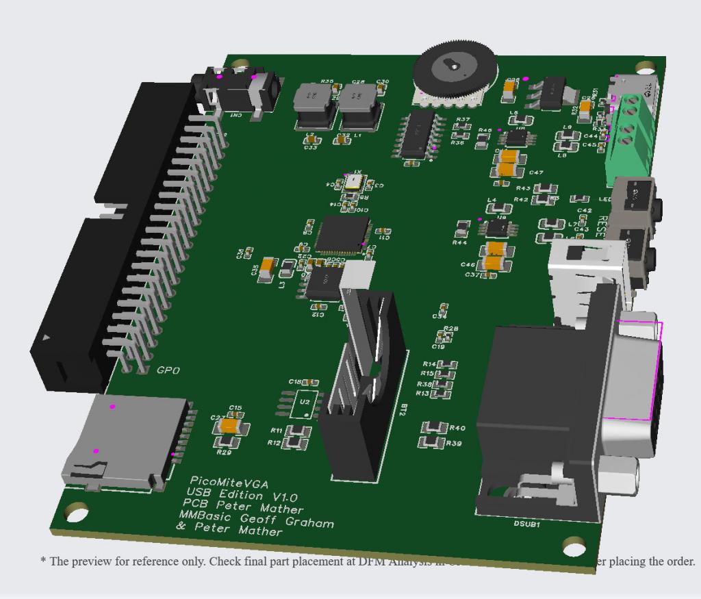 Schematic d526a77b-1cb1-44b9-a0d7-183d33be6519.pdf Price for 5-off fully built from JLC is just £66 + shipping. Bit cheaper than the CMM1 and CMM2!!! Edited 2024-01-27 19:55 by matherp |
||||
| Mixtel90 Guru Joined: 05/10/2019 Location: United KingdomPosts: 8911 |
Last time I was looking for a CR1220 I could only find them from the big component suppliers (with silly postage charges) and ebay. Nowhere round here even knew that size existed. I'm not that reassured about "widely available". :) I agree though, the CR2032 is a monster. Someone told me that the CR1220 is used in some car key thingies. If so, a car accessories place might be an idea. We haven't got one locally so I didn't try. Mick Zilog Inside! nascom.info for Nascom & Gemini Preliminary MMBasic docs & my PCB designs |
||||
| vegipete Guru Joined: 29/01/2013 Location: CanadaPosts: 1180 |
Could you check something on that circuit diagram? If you follow the the signal from pin 4 of the volume pot, it is connected through a 10uF cap to L4, then in series through C37 to U9 pin 3. This differs from the other channel. Pot pin 2 only leads through C39 to U8 pin 3. Visit Vegipete's *Mite Library for cool programs. |
||||
| matherp Guru Joined: 11/12/2012 Location: United KingdomPosts: 11540 |
Thanks - it wasn't the only error in the amp circuit  I haven't found in EasytEDA how to cut and paste a circuit element from one design to another so I was copying by hand from a known working one but made a mess of it. |
||||
| Volhout Guru Joined: 05/03/2018 Location: NetherlandsPosts: 5942 |
And U9 is powered between VCC and +5V. Volhout PicomiteVGA PETSCII ROBOTS |
||||
| matherp Guru Joined: 11/12/2012 Location: United KingdomPosts: 11540 |
Hopefully now all correct and all routed ready to get built. Because I needed so much edge space I've got room for a flat mounted CR2032 to please the punters. The PCB is 100x70 and double sided so current price at JLC is £1.57 for 5 - how can they make them for that? Total price for 5 fully built less the RTC chip is £63.25 + shipping so £12.65 each  5fe4d051-105c-4f94-bc7d-ce5994dfde16.pdf 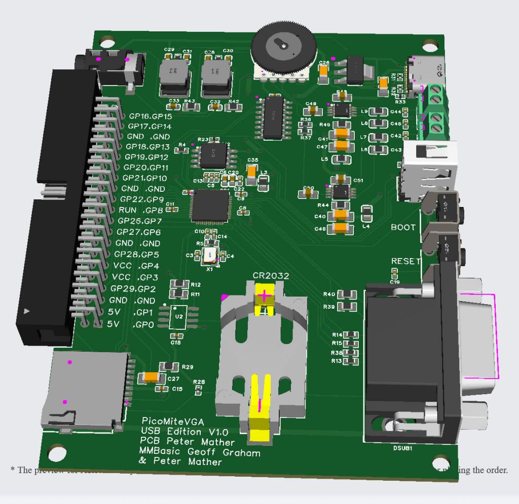 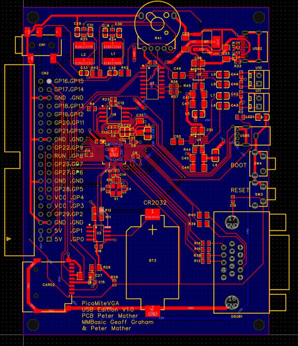 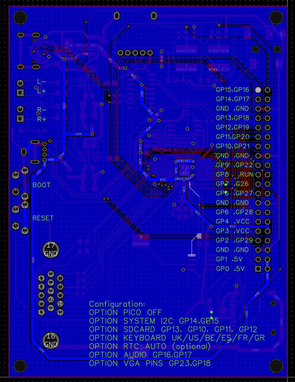 Edited 2024-01-28 04:55 by matherp |
||||
| thwill Guru Joined: 16/09/2019 Location: United KingdomPosts: 4369 |
As always, in awe, but also:  Is it designed with any particular enclosure in mind ? Best wishes, Tom MMBasic for Linux, Game*Mite, CMM2 Welcome Tape, Creaky old text adventures |
||||
| vegipete Guru Joined: 29/01/2013 Location: CanadaPosts: 1180 |
Shipping is a bit killer, but these aluminum housings would be nice, except the side lengths are reversed.  Visit Vegipete's *Mite Library for cool programs. |
||||
| Bleep Guru Joined: 09/01/2022 Location: United KingdomPosts: 810 |
Hi Peter, If you were to order up 5, I'd be up for one, if you had any spare to buy. :-) You can sort of see how the RP2040 geek can be sold for just over £8 Regards Kevin Edited 2024-01-28 06:24 by Bleep |
||||
| Mixtel90 Guru Joined: 05/10/2019 Location: United KingdomPosts: 8911 |
Cases are a pain, Pete. Really you have to start with a rough board layout to see where you want connectors then find a case that's readily available and that will accept connectors where you want them. Then you can start to design the board. Either that or simply accept that most people won't be bothered with a case (as I did with PicoMite VGA Basic and Sweetie-Pi.coMite). This time round (PicoGAME 4) I'm opting for the CMM2 case, but even that's a pain... I do like those aluminium extrusion cases though. I've built a couple of projects in similar ones. The screws for the end panels are a bit nasty (seriously? Countersunk screws in non-countersunk holes?). Much nicer if you can put some better screws in. Mick Zilog Inside! nascom.info for Nascom & Gemini Preliminary MMBasic docs & my PCB designs |
||||
bigmik Guru Joined: 20/06/2011 Location: AustraliaPosts: 2981 |
Hi Peter, All, Just a suggestion if it’s not too late, add 2 pads in parallel with each of the screw jacks for internal speakers in case someone want them internal to the box rather than externally connected. Regards, Mick Mick's uMite Stuff can be found >>> HERE (Kindly hosted by Dontronics) <<< |
||||
| phil99 Guru Joined: 11/02/2018 Location: AustraliaPosts: 3294 |
1) They could just omit them and solder the wires on. 2) Turn them around so the wires are on the inside. |
||||
| Page 1 of 13 |
|||||
| The Back Shed's forum code is written, and hosted, in Australia. | © JAQ Software 2026 |
