
|
|
Forum Index : Electronics : 150V 45A MPPT - roll your own
| Author | Message | ||||
| rogerdw Guru Joined: 22/10/2019 Location: AustraliaPosts: 906 |
Thanks for that explanantion Peter, I'm slowly learning how it all works. I do now have three arrays and three mppt's connected. I will add more panels and the fourth mppt soon. I certainly wasn't suspecting anything wrong with this third mppt ... I was just a little disappointed in the output from the 3kW of panels I put up on the weekend. I did try shutting off the first two to see what this would do on its own ... and I also swapped one of the chokes over as on this third one I fitted a couple extra turns than the earlier ones. Anyway I PULLED A CLANGER ... just on dusk tonight I thought I'd check my combiner box to see if I'd made some sort of mistake there. Pulled all the fuses down ... and there were TWO FUSES MISSING!!! I hadn't even checked. I knew I was a couple short ... but I thought they were in the last box that hasn't been connected yet. So if my output was only about 75% of what I was expecting ... THAT'S BECAUSE ONLY 75% WAS CONNECTED!!! Duh!!!  Man, and I had gone through a hundred scenarios as to what I should do ... buy a heap of better panels, pull down the ones I just put up and sell them ... haha, what a dill! And to add insult to injury, here's a picture of the output from the first two mppt's going strong at one stage today, while the third was lagging behind. Had the camera at the wrong angle, so the third display didn't show. Not sure I should run it this hard ... but it was cloudy and only intermittant. What's fascinating is that the first two lots of panels are old used 275 watt panels, two lots of 3.3kW ... and for short bursts they were pumping out just over that. I'm impressed. Great design, thanks man.  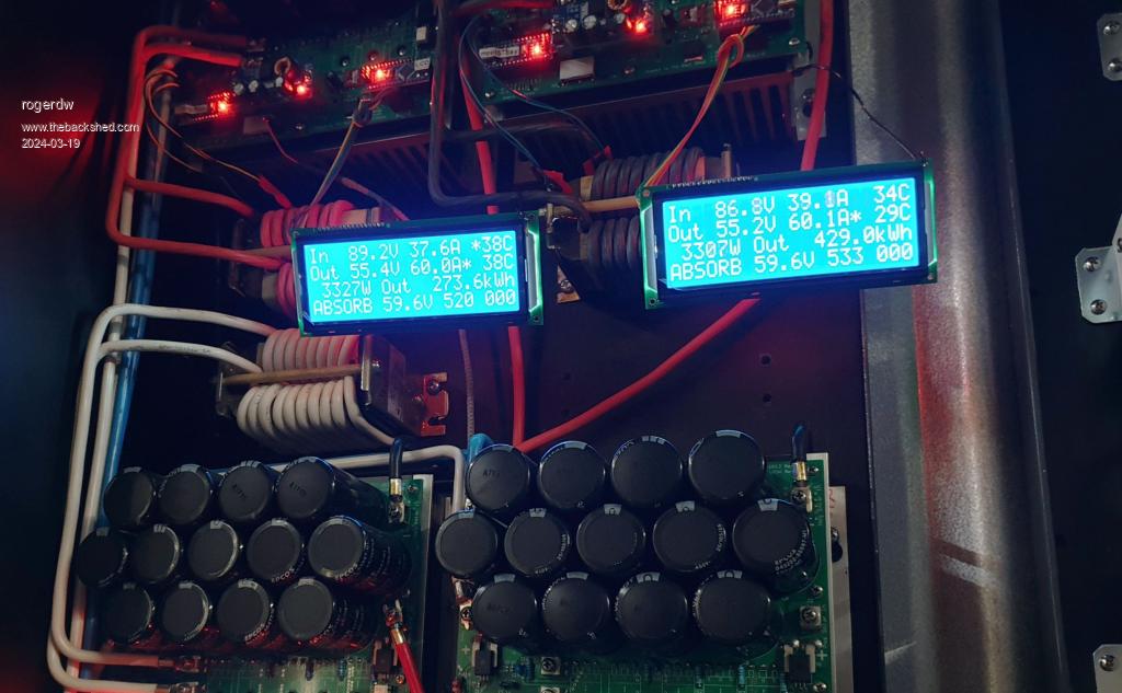 Cheers, Roger |
||||
| flyingfishfinger Senior Member Joined: 12/09/2020 Location: United StatesPosts: 118 |
Looks very nice! What version of the MPPT board are you using? It looks a bit different from the one I referenced / built - you've got the Nano(s) on board! Cheers, R |
||||
| rogerdw Guru Joined: 22/10/2019 Location: AustraliaPosts: 906 |
Thanks very much. It was one of Wiseguy's boards that (with his blessing and help) I added extra room on the bottom to fit both nano's and 12v and 5v supplies. It was what I was working on way back here ... in this thread. Like most things I do it took me forever to get it done and built but finally there now. I have all four up and pumping well and charging a 48v 980Ah forklift battery. And that is running my Warpverter. Cheers, Roger |
||||
| flyingfishfinger Senior Member Joined: 12/09/2020 Location: United StatesPosts: 118 |
Oh right, that one! Yes I remember that discussion. I'm glad it works nicely, good job! R |
||||
| mab1 Senior Member Joined: 10/02/2015 Location: United KingdomPosts: 245 |
Possibly spotted a very minor error in (i think) the latest version of the code.ZIP (serial LCD version): TID=12027&P=47#212592latest version serial LCD it seemed to do an extra MPPT scan every couple of mins at the 55sec mark ,but i spotted this in the code: if ( timeout_check(8,1)) { cal_sensor_count ++; if (cal_sensor_count > 1) // should be 60 for an hour. testing will have it at 2 or something { cal_sensor_count = 0; // one hour is up time to recal current sensor zero points if (track_mode != NIGHT) { //stop it But as the Comment says "should be 60 for an hour" so is easy enough to change. |
||||
| poida Guru Joined: 02/02/2017 Location: AustraliaPosts: 1432 |
it's an easy fix alright. Thanks for reading through the code and finding this. latest version with the fix: mpptv5_BV_tempco_day_totals_current_sense_recal.zip wronger than a phone book full of wrong phone numbers |
||||
| nickskethisniks Guru Joined: 17/10/2017 Location: BelgiumPosts: 462 |
Hi Peter is there a reason you choose for the software serial instead of the already present hardware serial interface on the arduino board? I ask because I want to add a can interface to the mppt controllers, I need pins 10 and 11 free for the spi bus. The idea was to add it on the nano that does the uart/I²C conversion for the display. The hardware should not conflict the spi bus, I'm not sure about the serial library. Do you think this would work, or am I missing something? Thanks. Edited 2024-05-12 06:42 by nickskethisniks |
||||
| -dex- Senior Member Joined: 11/01/2024 Location: PolandPosts: 101 |
Is there any update on this for mpptv5_highside_ntc version/serial lcd? |
||||
| The Back Shed's forum code is written, and hosted, in Australia. | © JAQ Software 2025 |
