
|
|
Forum Index : Electronics : AndyMc's OZ/MAD/NANO Inverter Build
| Page 1 of 3 |
|||||
| Author | Message | ||||
| andymc70 Regular Member Joined: 30/06/2019 Location: AustraliaPosts: 43 |
Hello All I finally got around to putting my build on here. Thanks to RenewableMark for all the help so far and encouragement to do this. Thanks to Poida for the Nanoboards. Thanks to Ryan for offer a Madness Power Board. So i am trying to build at least a 6kw OZ MAD NANO Inverter to run the whole house. I have 48V DIY Powerwall setup to run it. I purchased 2x3kw Aeroshape Inverters awhile ago and have started follow Marks build. I have put there torroids ptogether and the measurement where 208OD, Ā100ID and 140 High. After reading all the forums, i figured that 120 turns would be ok and easy to count. So i have done 3 layers and i did the light bulb test after the 2nd layer, unfortunately the only thing i could find was light bulb wise was a LED, not sure if that ok or not. I also did not realise i had to shorten the light bulb out until after i have completed my 3rd layer. So when i did my final testing these are what i had on my leads (1)239, (2)237 and (3)239. When i did my inital test with (1) and (2) there was a 0.6 potential between them, (without the shorten light bulb). When i test between (3) and Ājoined (1)(2) the potential voltage is 1v. I havent finished off the 3rd layer yet. I wondering if its ok to finish it off or do i need to fix up to a 0v potential. I will add picture and questions later. Thanks for your support Andy Edited 2020-09-24 16:47 by andymc70 |
||||
| Warpspeed Guru Joined: 09/08/2007 Location: AustraliaPosts: 4406 |
There will be 240v and 120 turns, so two volts per turn. I think layer two may possibly be one turn less than layers one and three ? Cheers, ĀTony. |
||||
| andymc70 Regular Member Joined: 30/06/2019 Location: AustraliaPosts: 43 |
Thanks Warspeed, that makes sense, i think i took a turn off [2] to make it match closer with [1], but i am thinking the measurements where wrong due to not shorting the bulb. Now i am hoping i can add an extra turn on [2] as taking 1 of [1] will be painful. What are the chances i could just add a turn on [2] on the same layer as [3] or do i need to cut back the mylar and place it on the [2] layer, reapply resin and mylar and then finish [3] layer. [i am hoping i can test it on layer [3] at least]. Dam great start to the build. Andy |
||||
| wiseguy Guru Joined: 21/06/2018 Location: AustraliaPosts: 1296 |
Don't stress whilst waiting for an answer Andy (or start undoing your windings to fix), I'm sure Tony will soon answer you with a confirmation to just add 1 more turn to winding 2 to solve your issue. If that's the worst that happens during your build it is not a bad result at all ! If at first you dont succeed, I suggest you avoid sky diving.... Cheers Mike |
||||
| hugocamaras Newbie Joined: 12/04/2019 Location: BrazilPosts: 24 |
Hello! What measures should I use on a toroidal core for an 8000 watt inverter? 240v and 127v (Brazil) |
||||
renewableMark Guru Joined: 09/12/2017 Location: AustraliaPosts: 1679 |
Hugo, build threads get complicated enough without going off and answering other peoples questions on totally different setups. Please start a thread of your own. Andy, I don't know how you are doing this with an LED, probably wiser to follow the well beaten path and use a incandescent bulb, you can probably get them from bunnings, just had a look and their web site is annoying. RS have them though. About the extra turn, dunno the answer to that. When I do a winding, leave 1m extra wire loose. Do the test confirm it's all equal. Then wind on an extra turn and re do the test, this should add 2v, so just another confirmation your initial test/turns count was correct, probably not needed though. Do the test a couple of times and make sure no big loads are being turned on in the house while you are doing it. If someone starts the dryer and the oven gets turned on mid test it might throw it out. Take your time and if not sure just ask, they are a very friendly bunch here. Also be bloody careful with 240v. Cheers Caveman Mark Off grid eastern Melb |
||||
| Warpspeed Guru Joined: 09/08/2007 Location: AustraliaPosts: 4406 |
Andy, just add one more turn, anywhere it will fit best. Jut do whatever is easiest, an extra turn from layer two added to layer three will be fine. Cheers, ĀTony. |
||||
| Warpspeed Guru Joined: 09/08/2007 Location: AustraliaPosts: 4406 |
Just realised why I have not been getting e-mail notifications. Had not noticed the addition of the blue subscribe box. Cheers, ĀTony. |
||||
| andymc70 Regular Member Joined: 30/06/2019 Location: AustraliaPosts: 43 |
Your not wrong Mark, i am over the click and collect, i am like 5min from bunnings but i have to wait 2 days to collect anything. By the way the LED works, it was my laziest of reading forums thoroughly that i missed your comment on shorting the bulb out after it starts. I should have realise when i read soft start. Thanks Tony will do that now. |
||||
| renewableMark Guru Joined: 09/12/2017 Location: AustraliaPosts: 1679 |
This is a good reference for winding. BTW I used to use a switch to run the globe by itself then short it out, one time I started it with the switch in the shorted position, and found it didn't trip fuses, the bulb just flashed briefly. Try it if you like but keep in mind I had a incandescent bulb that may have softened the surge. Edited 2020-09-25 11:26 by renewableMark Cheers Caveman Mark Off grid eastern Melb |
||||
| renewableMark Guru Joined: 09/12/2017 Location: AustraliaPosts: 1679 |
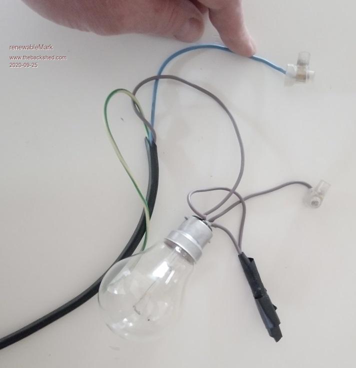 Screw connectors are for winding connections. 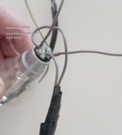 This is the rig I used, it has a 75w bulb. Where the black tape is, there used to be a switch. I don't use that anymore and they are shorted together. With the bulb still in place it just gives a quick flash. Cheers Caveman Mark Off grid eastern Melb |
||||
| andymc70 Regular Member Joined: 30/06/2019 Location: AustraliaPosts: 43 |
How many layers? I am also wondering should i add another layer and take it up to 4. What are people thoughts on this. Also the primary wiring, i am wondering what i should use. i have a few thoughts: [1] i think Mark used this Welding cable 50mm2, would 50mm2 be big enough or do i need to go to the 70mm2. I think you remove the orange outer layer to reduce the thickness. [2] Tycab cabling wondering what size is recommended. Tycab cabling in Melbourne [3] Some how using the similar wire used in the secondary to the desired thickness. I can not find if anyone else is doing that, a link would be appreciated if its done. NO COST So working the Primary turn i used the 1:8 ratio, which would be 120/8 equal 15. So the number of Primary turns is 15, so if i am using MADNESS Powerboard and Poida Control board, what the voltage i am looking for on the Primary. Any other thoughts on the Primary would be great. Thanks Andy |
||||
| andymc70 Regular Member Joined: 30/06/2019 Location: AustraliaPosts: 43 |
So i joined a length and heat shrink it and then wrapped around the core. BINGO all 3 are now 246v so problem solved. Thanks Tony. 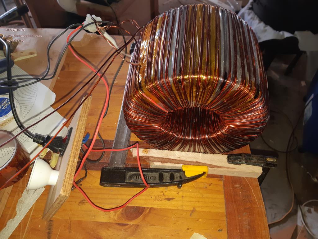 |
||||
| Warpspeed Guru Joined: 09/08/2007 Location: AustraliaPosts: 4406 |
The empty toroid started out having a 100mm diameter hole. You can keep adding layers until the remaining hole shrinks down to 70mm. In theory that will provide equal copper areas for the primary and the secondary in the available space. Ā It never quite works out being exact, but 70.71% is a good figure to aim for. If your secondary/primary ratio is 8:1 Āand your secondary voltage is 240v, then the primary will be 30.0v rms. The PEAK voltage in the primary will be about 42.42 volts, and the inverter has to have enough dc from the battery to create those peaks. Flat out, there are going to be voltage drops everywhere, which might all add up to two or three volts. So minimum battery voltage to make 240v might be about very roughly 45 volts dc. Edited 2020-09-25 14:38 by Warpspeed Cheers, ĀTony. |
||||
| Warpspeed Guru Joined: 09/08/2007 Location: AustraliaPosts: 4406 |
Thinking about the primary..... Assuming you end up with a 70mm hole (it may be different) and 15 turns are needed. We go to our trusty holes within holes internet calculator. https://www.engineeringtoolbox.com/smaller-circles-in-larger-circle-d_1849.html Plug in the numbers, and we find that 15 wires with a maximum diameter of 15mm will fit through a 70 mm hole. We go to the TYCAB website and look up automotive starter cable. https://www.tycab.com.au/battery-starter/ click on specifications. We see that 64mm/sq has a diameter of 14.5mm, and that should work pretty well. Edited 2020-09-25 14:57 by Warpspeed Cheers, ĀTony. |
||||
| renewableMark Guru Joined: 09/12/2017 Location: AustraliaPosts: 1679 |
Nah I ended up using 70mm welding cable with the outer orange insulation taken off, here At first I wound it myself to 70mm2 here In hindsight I would buy the welding cable any day, but since us Vic's have so much spare time now it's up to you. Cheers Caveman Mark Off grid eastern Melb |
||||
| Warpspeed Guru Joined: 09/08/2007 Location: AustraliaPosts: 4406 |
The big cable is not exactly cheap to buy, and it would be a pity to end up being a bit short in length. One way to estimate the required length and be absolutely certain, would be to first buy some 15mm diameter rope, and experiment with that. Cheers, ĀTony. |
||||
| andymc70 Regular Member Joined: 30/06/2019 Location: AustraliaPosts: 43 |
Your 100% correct Tony very expensive. So like Mark said being in lock down and our crap postal system at the moment i have plenty of time. So i thought i have ago at twisting my own {my body is regretting that decision at the moment, but nothing a few days rest wont fix, LOL} I got an old extension cable and ran it thru the toroid 15 times, took a measurement of voltage. TONY spot on 30.4 volts, i then place a cable tie about 0.5m from the end to get my length. It was very losely wound so after measuring it was around 7.6m. . So i followed the link provided by mark, plus my experience of making twisted wire for my POWERWALL, i twisted about 8.5m of 22 wires, i orderd some heat shrink {who know when it will get here}to go over it. Bit annoyed 2 wires came lose, so its not as good as i would have liked but i think it will work well enough. The diameter is around 13mm NOW i have to ask how do i put the LUGs on as the enamel isnt easy to remove and i am worried that i can remove the outer enamel but how do i remove the inner ones enamels.{I hope that makes sense}. Also my inner hole is around 72mm at the moment, i think my first layer wasnt as good as the other 2 layers, and i have a lump around where all the wires are connect on the outside, so i wont add another layer. Now what to do next? I was thinking getting started on the chokes. I am still waiting for my components to arrive, so i can not start on any boards. Andy |
||||
| Warpspeed Guru Joined: 09/08/2007 Location: AustraliaPosts: 4406 |
Great progress Andy ! Cheers, ĀTony. |
||||
| renewableMark Guru Joined: 09/12/2017 Location: AustraliaPosts: 1679 |
Andy what mm2 wire did you use? Lump on the outside makes no difference at all BTW. You get better at doing these, next one you'll get 4 layers and 70mm hole left. Cheers Caveman Mark Off grid eastern Melb |
||||
| Page 1 of 3 |
|||||
| The Back Shed's forum code is written, and hosted, in Australia. | © JAQ Software 2026 |
