
|
|
Forum Index : Microcontroller and PC projects : PicoMite Alpha Firmware - a27 onwards - starting on displays
| Author | Message | ||||
| Mixtel90 Guru Joined: 05/10/2019 Location: United KingdomPosts: 8909 |
@lizby I'm just using a 68R resistor to +5v. It's one I just had hanging around from a previous experiment. :) Hmmm... With a36 loaded all seems ok and Calibrate has worked. Loaded a38 and... > flash erase all > var clear > option reset > option system spi 4,5,1 > option sdcard 2,15 > files Error : SD Card not found > Edited 2021-06-26 07:13 by Mixtel90 Mick Zilog Inside! nascom.info for Nascom & Gemini Preliminary MMBasic docs & my PCB designs |
||||
| lizby Guru Joined: 17/05/2016 Location: United StatesPosts: 3783 |
One way: Pico 2x20 20x2 Pico GP# # USB # GP# I2C0 SDA 1 | 0 3 | 40 VBUS I2C0 SCK 2 | 1 5 | 39 VSYS GND 3 | | 38 GND SPI_SCK 4 | 2 19 | 37 3V3_EN SPI_MOSI 5 | 3 21 | 36 3V3(out) SPI_MISO 6 | 4 21 Pico | 35 ADC_VREF SPI_CS_SD 7 | 5 37 I/O 12 28 | 34 Digital/ADC2 o T_IRQ GND 8 | | 33 GND/ADCGND o SPI_MISO p18 9 | 6 18 22 27 | 32 Digital/ADC1 o SPI_MOSI p24 10 | 7 24 29 26 | 31 Digital/ADC0 o T_CS COM2:Tx 11 | 8 16 | 30 RUN o SPI_SCK COM2:Rx 12 | 9 11 36 22 | 29 T_IRQ o SPI_MISO GND 13 | | 28 GND o 68R TO 3V3 I2C1 SDA 14 | 10 27 33 21 | 27 T_CS o SPI_SCK I2C1 SCK 15 | 11 28 15 20 | 26 LCD_D/C o SPI_MOSI (SPI2_MISO) 16 | 12 35 28 19 | 25 LCD_RST o LCD_D/C p31 17 | 13 31 27 18 | 24 LCD_CS o LCD_RST GND 18 | | 23 GND o LCD_CS (SPI2_SCK) 19 | 14 40 22 17 | 22 COM1:Rx o 0V (SPI2_MOSI) 20 | 15 38 7 16 | 21 COM1:Tx o 3V3 GP# # # GP# Pico 2x20 20x2 Pico PicoMite, Armmite F4, SensorKits, MMBasic Hardware, Games, etc. on FOTS |
||||
| matherp Guru Joined: 11/12/2012 Location: United KingdomPosts: 11500 |
Doesn't achieve anything. Tokenising a program kills memory so you couldn't then chain the program. Given that load x, flash save x is hardly onerous. There are differences in I/O e.g. use of SETPIN so there is no reason to make changes that break the link from the underlying H/W pin definitions I thought I'd fixed that in the recent releases? Sounds possible Not my objective for the PicoMite as an embedded controller. The PIC32MZ has all this, supports SSD1963 displays and is faster (including 64-pin version) - why replicate 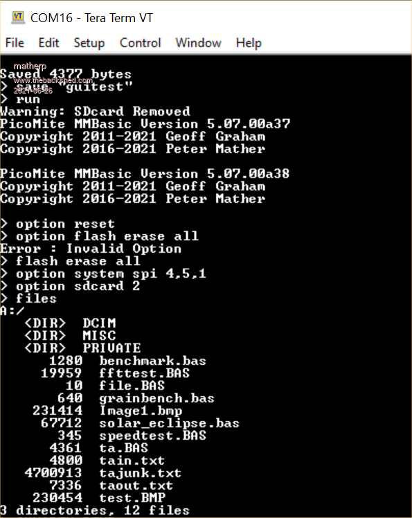 Edited 2021-06-26 07:44 by matherp |
||||
| Mixtel90 Guru Joined: 05/10/2019 Location: United KingdomPosts: 8909 |
or: Display PicoMite T_IRQ 15 T_DO 1 T_DIN 5 T_CS 16 T_CLK 4 MISO 1 LED 68R resistor to VBUS SCK 4 MOSI 5 DC 20 RESET 19 CS 17 GND GND VCC VBUS Then use these commands to initialise it: OPTION LCDPANEL ILI9341 L,20,19,17 OPTION TOUCH 16,15 Then test it with: GUI TEST LCDPANEL (use Ctrl-C to stop it) and GUI TEST TOUCH (write on the screen with a stylus, Ctrl-C to stop) TEXT 100,100,"Hello World!" to put something on screen. Like I said, there's no one right way. :) Mick Zilog Inside! nascom.info for Nascom & Gemini Preliminary MMBasic docs & my PCB designs |
||||
| panky Guru Joined: 02/10/2012 Location: AustraliaPosts: 1127 |
@mixtel90 Mick, in you Pico docs under a21 the entry line referencing TOUCH has IRQ and CS the wrong way round - this is from Peters 'Coming .....' entry so just a typo and long since bypassed but it caught me out. All other references seems to be good TOUCH cspin, irqpin [,beep pin]. Thanks for the Pico docs, they have been invaluable for me. Doug. ... almost all of the Maximites, the MicromMites, the MM Extremes, the ArmMites, the PicoMite and loving it! |
||||
| Mixtel90 Guru Joined: 05/10/2019 Location: United KingdomPosts: 8909 |
Thanks, Doug. I've fixed that now. Glad you've found it useful. :) Updated to a38: PicoMite docs a38.zip ** Any ideas folks? ** I *think* I might have found my problem with losing the SD card when T_CS is connected. The pullup on that signal is either missing or too weak. I've added a 10k pullup to 3.3v and reloaded a38. I can now read the SD card. Display is working. Touch calibration screen appears but same problem. This time I noted that *any* touch on the screen brings up the error message, whether in calibration mode or not, so touch is definitely being detected. Tried a 10k pullup (and pulldown just in case) on T_IRQ too but that's not helped. Swapped back to a36 and SD card, display & calibration all set up & work fine. Loaded a37. SD card and display are fine. Same problem on attempting calibration. PicoMite MMBasic Version 5.07.00a37 Copyright 2011-2021 Geoff Graham Copyright 2016-2021 Peter Mather > option list OPTION SDCARD GP1, 10 OPTION SYSTEM SPI GP2,GP3,GP0 OPTION LCDPANEL ILI9341, RLANDSCAPE,GP15,GP14,GP13 OPTION TOUCH GP12,GP11 > Just tried a different Pico with the same setup and result as above. Adding OPTION CPUSPEED 250000 gives the same error but faster. :) . Edited 2021-06-26 18:41 by Mixtel90 Mick Zilog Inside! nascom.info for Nascom & Gemini Preliminary MMBasic docs & my PCB designs |
||||
| lizby Guru Joined: 17/05/2016 Location: United StatesPosts: 3783 |
Thank you for this. I also had it T_IRQ, T_CS, and that was the reason I got no response to touching the target. Unfortunately, now when I touch the target, the response I get is not good: screen goes blank and: > gui calibrate Error : Touch not calibrated This is with an ILI9488--I'll try with the ILI9341. And as with Mixtel90, any subsequent touch gives multiple "Error : Touch not calibrated" messages--4 of them in my case. Tried again and got to the second target before getting the error. Tried again and got to the 4th target, but still getting the error after clicking it. After multiple further attempts which failed at various targets, it completed: > Error : Touch not calibrated > gui calibrate Done. No errors Deviation X = 0, Y = 3 (pixels) > option list OPTION SDCARD GP5, 10 OPTION SYSTEM SPI GP2,GP3,GP4 OPTION SYSTEM I2C GP10,GP11 OPTION LCDPANEL ILI9488, LANDSCAPE,GP20,GP19,GP18 OPTION RTC AUTO ENABLED OPTION GUI CONTROLS 59 OPTION MEMORY 60160, 100608 OPTION TOUCH GP21,GP22 GUI CALIBRATE 0, 3950, 3882, -1244, -859 > GUI TEST TOUCH works. ~ Edited 2021-06-26 21:41 by lizby PicoMite, Armmite F4, SensorKits, MMBasic Hardware, Games, etc. on FOTS |
||||
| lizby Guru Joined: 17/05/2016 Location: United StatesPosts: 3783 |
With a38, FLASH SAVE # is not working for me: > list ' Demonstration program for the Micromite+ . . . Sub TouchUp Select Case Touch(LASTREF) ' use the last reference Case pb_test ' was it the test button CtrlVal(led_alarm) = 0 ' turn off the LED End Select End Sub > flash list Slot 1 available Slot 2 available Slot 3 available Slot 4 available Slot 5 available Slot 6 available Slot 7 available Slot 8 available Slot 9 available Slot 10 available > flash save 9 > flash list Slot 1 available Slot 2 available Slot 3 available Slot 4 available Slot 5 available Slot 6 available Slot 7 available Slot 8 available Slot 9 available Slot 10 available > list ''''''''''''''''''''''''''''''''''''''''''''''''''''''''''''''''' ' Demonstration program for the Micromite+ . . . I swapped picos in my perfboard because I didn't want to lose the working settings for the ILI9488, and put in the ILI9341. After setting up the options again, and double-checking the right order for the TOUCH pins, with GUI CALIBRATE I get the first target, but it doesn't respond to a touch. ~ Edited 2021-06-26 22:27 by lizby PicoMite, Armmite F4, SensorKits, MMBasic Hardware, Games, etc. on FOTS |
||||
| Mixtel90 Guru Joined: 05/10/2019 Location: United KingdomPosts: 8909 |
@matherp Is power now running in PFM or PWM? You mentioned in a35 that it's now permanent, but you didn't say which way. I assume it's PWM? OPTION POWER doesn't appear to do anything now (I'd never used it so I assume it disappeared at a35). I'm wondering if I have a power issue. I've ordered a powered usb hub just in case. This second Pico is very unreliable enumerating unless T_CS is disabled. Mick Zilog Inside! nascom.info for Nascom & Gemini Preliminary MMBasic docs & my PCB designs |
||||
| matherp Guru Joined: 11/12/2012 Location: United KingdomPosts: 11500 |
Default after option reset is PFM |
||||
| Mixtel90 Guru Joined: 05/10/2019 Location: United KingdomPosts: 8909 |
Thanks. It's not the extra load of PWM that's doing it then. Is there any way we could read ADC3 (VSYS) and GP24 (VBUS)? Mick Zilog Inside! nascom.info for Nascom & Gemini Preliminary MMBasic docs & my PCB designs |
||||
| matherp Guru Joined: 11/12/2012 Location: United KingdomPosts: 11500 |
a39 PicomiteV5.07.00a39.zip Fixes a bug in FLASH SAVE and a race condition in the GUI processing |
||||
| Plasmamac Guru Joined: 31/01/2019 Location: GermanyPosts: 620 |
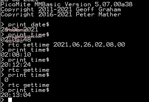 print time$ Error after not touching teraterm for > 10 h to test the rtc. > option list OPTION SYSTEM I2C GP20,GP21 OPTION RTC AUTO ENABLED make some new tests. Edited 2021-06-27 06:30 by Plasmamac Plasma |
||||
| Plasmamac Guru Joined: 31/01/2019 Location: GermanyPosts: 620 |
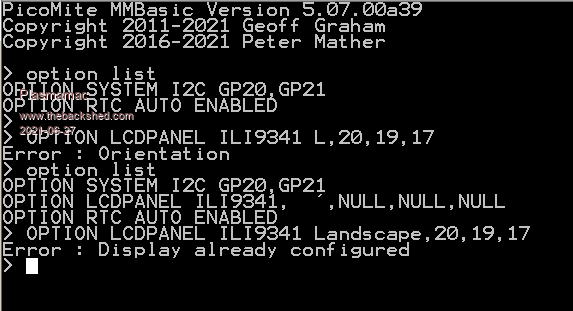 cant setup the lcd after a mistyped (?) configuration without disconnect the usb / reset. Plasma |
||||
| Plasmamac Guru Joined: 31/01/2019 Location: GermanyPosts: 620 |
. Edited 2021-06-27 06:51 by Plasmamac Plasma |
||||
| Mixtel90 Guru Joined: 05/10/2019 Location: United KingdomPosts: 8909 |
@Plasmamac You should be able to remove the previous lcd setup using OPTION LCDPANEL DISABLE then enter a new configuration. You have to do this whenever you make changes to an lcd. Mick Zilog Inside! nascom.info for Nascom & Gemini Preliminary MMBasic docs & my PCB designs |
||||
| Plasmamac Guru Joined: 31/01/2019 Location: GermanyPosts: 620 |
ok i forget the"," OPTION LCDPANEL ILI9341,L,20,19,17 disable the lcd works also. finally the lcd works fine , thx for the help thx Edited 2021-06-27 07:33 by Plasmamac Plasma |
||||
| lizby Guru Joined: 17/05/2016 Location: United StatesPosts: 3783 |
Using the pico which on which I had not been able to complete GUI CALIBRATE for an ILI9341, I plugged in a new ILI9488 and set it up. It took about 10 attempts at GUI CALIBRATE before it succeeded. Then I ran a guidemo.bas which had been modified for 480x320:  I tried SAVE IMAGE "gui480.bmp", but the file was all white--I guess because of the non-working status of MISO on the ILI9488 (I had snipped off the pin). ''''''''''''''''''''''''''''''''''''''''''''''''''''''''''''''''' ' Demonstration program for the Micromite+ ' It does not do anything useful except demo the various controls ' ' Geoff Graham, October 2015 ' Mod to 480x320 by Lance Benson (lizby) April 2021, June 2021 ''''''''''''''''''''''''''''''''''''''''''''''''''''''''''''''''' 'Option Autorun On Option Explicit ' gui calibrate 'backlight 50 ' not available on pico Dim ledsY Colour RGB(white), RGB(black) ' reference numbers for the controls are defined as constants Const c_head = 1, c_pmp = 2, sw_pmp = 3, c_flow = 4, tb_flow = 5 Const led_run = 6, led_alarm = 7 Const frm_alarm = 20, nbr_hi = 21, nbr_lo = 22, pb_test =23 Const c_hi = 24, c_lo = 25 Const frm_pump = 30, r_econ = 31, r_norm = 32, r_hi = 33 Const frm_log = 40, cb_enabled = 41, c_fname = 42, tb_fname = 43 Const c_log = 44, cb_flow = 45, cb_pwr = 46, cb_warn = 47 Const cb_alarm = 48, c_bright = 49, sb_bright = 50 ' now draw the "Pump Control" display CLS dim integer f1=4,f2=5 if mm.device$="RP2040 PicoMite" then f1=1:f2=2 GUI Interrupt TouchDown, TouchUp ' display the heading Font f2 : GUI Caption c_head, "Pump Control", 10, 0 Font f1 : GUI Caption c_pmp, "Pump", 10, 32, , RGB(brown) ' now, define and display the controls ' first display the switch Font f1 GUI Switch sw_pmp, "OFF|ON", 10, 57, 115, 50, RGB(white),RGB(brown) CtrlVal(sw_pmp) = 1 ' the flow rate display box Font f1 : GUI Caption c_flow, "Flow Rate", 5, 109,, RGB(brown),0 Font f2 : GUI Displaybox tb_flow, 5, 130, 147, 37 CtrlVal(tb_flow) = "20.1" ' the radio buttons and their frame Font f2 : GUI Frame frm_pump, "Power", 5, 180, 157, 135,RGB(200,20,255) Font f1 GUI Radio r_econ, "Economy", 22, 210, 12, RGB(230, 230, 255) GUI Radio r_norm, "Normal", 22, 247 GUI Radio r_hi, "High", 22, 285 CtrlVal(r_norm) = 1 ' start with the "normal" button selected ' the alarm frame with two number boxes and a push button switch Font f2 : GUI Frame frm_alarm, "Alarm", 172, 142, 137, 172,RGB(green) Font f1 GUI Caption c_hi, "Hi:", 180, 180, LT, RGB(yellow) GUI Numberbox nbr_hi, 220,MM.VPos-6,70,MM.FontHeight+6,RGB(yellow),RGB(64,64,64) GUI Caption c_lo, "Lo:", 180, 222, LT, RGB(yellow),0 GUI Numberbox nbr_lo, 220,MM.VPos-6,70,MM.FontHeight+6,RGB(yellow),RGB(64,64,64) GUI Button pb_test, "TEST", 187, 260, 105, 37,RGB(yellow), RGB(red) CtrlVal(nbr_lo) = 15.7 : CtrlVal(nbr_hi) = 35.5 ' draw the two LEDs Const ledsX = 187, coff = 75 ' define their position ledsY = 65 : GUI LED led_run, "Running", ledsX, ledsY, 15, RGB(green) ledsY = ledsY+37 : GUI LED led_alarm, "Alarm", ledsX, ledsY, 15, RGB(red) CtrlVal(led_run) = 1 ' the switch defaults to on so set the LED on ' the logging frame with check boxes and a text box Colour RGB(cyan), 0 Font f2 'GUI Frame frm_log, "Log File", 210, 10, 110, 158, RGB(green),0 GUI Frame frm_log, "Log File", 323, 15, 150, 240, RGB(green) Font f1 GUI Checkbox cb_enabled, "Log On", 340, 30, 30, RGB(cyan) GUI Caption c_fname, "File Name", 340, 67 GUI Textbox tb_fname, 340, 90, 125, 30, RGB(cyan), RGB(64,64,64) GUI Caption c_log, "Record:", 340, 127, , RGB(cyan), 0 GUI Checkbox cb_flow, "Flow", 348, 150, 30 GUI Checkbox cb_alarm, "Alarms", 348, 180, 30 GUI Checkbox cb_warn, "Warnings", 348, 210, 30 CtrlVal(cb_enabled) = 1 CtrlVal(tb_fname) = "LOGFILE.TXT" ' define and display the spinbox for controlling the backlight GUI Caption c_bright, "Back Light", 358, 262,,RGB(200,200,255),0 ' GUI Spinbox sb_bright, 210, 210, 110, 25,,,10, 10, 100 GUI Spinbox sb_bright, 333, 282, 135, 37,,,10, 10, 100 CtrlVal(sb_bright) = 100 ' All the controls have been defined and displayed. At this point ' the program could do some real work but because this is just a ' demo there is nothing to do. So it just sits in a loop. Do : Loop ' the interrupt routine for touch down ' using a select case command it has a different process for each ' control Sub TouchDown Select Case Touch(REF) ' find out the control touched Case cb_enabled ' the enable check box If CtrlVal(cb_enabled) Then GUI Restore c_fname, tb_fname, c_log, cb_flow, cb_alarm, cb_warn Else GUI Disable c_fname, tb_fname, c_log, cb_flow, cb_alarm, cb_warn EndIf Case sb_bright ' the brightness spin box ' BackLight CtrlVal(sb_bright) ' not available on pico Case sw_pmp ' the pump on/off switch Print CtrlVal(sw_pmp) CtrlVal(led_run) = CtrlVal(sw_pmp) CtrlVal(tb_flow) = Str$(CtrlVal(sw_pmp) * 20.1) CtrlVal(r_norm) = 1 Case pb_test ' the alarm test button Open "Test.txt" For Append As #1 Print "File Opened" Print #1, "Hello World", Time$ Print "Hello World", Time$ Close #1 Print "File Closed" CtrlVal(led_alarm) = 1 ' GUI beep 250 ' on picomite, "Error: CLick option not set Case r_econ ' the economy radio button CtrlVal(tb_flow) = Str$(CtrlVal(sw_pmp) * 18.3) Case r_norm ' the normal radio button CtrlVal(tb_flow) = Str$(CtrlVal(sw_pmp) * 20.1) Case r_hi ' the high radio button CtrlVal(tb_flow) = Str$(CtrlVal(sw_pmp) * 23.7) End Select End Sub ' interrupt routine when the touch is removed Sub TouchUp Select Case Touch(LASTREF) ' use the last reference Case pb_test ' was it the test button CtrlVal(led_alarm) = 0 ' turn off the LED End Select End Sub PicoMite on FruitOfTheShed PicoMite, Armmite F4, SensorKits, MMBasic Hardware, Games, etc. on FOTS |
||||
| TrevorC Newbie Joined: 15/07/2020 Location: United KingdomPosts: 18 |
I am still have a problem with GUI CALIBRATE with version a39 and have found that after entering OPTION TOUCH GP21,GP20 I get an ERROR : Touch not calibrated when the lcd is touched without entering GUI CALIBRATE. Powering off and powering on results in the same error. The last version that I have working is a36. Settings below: Not sure where the 10 on OPTION SDCARD comes from. > option list OPTION SDCARD GP17, 10 OPTION SYSTEM SPI GP18,GP19,GP16 OPTION SYSTEM I2C GP0,GP1 OPTION LCDPANEL ILI9341, RLANDSCAPE,GP22,GP26,GP27 OPTION TOUCH GP21,GP20 |
||||
| Mixtel90 Guru Joined: 05/10/2019 Location: United KingdomPosts: 8909 |
The 10 in SDCARD is the default speed of 10MHz. You can set it lower or higher to suit your particular card. Mine works fine at 15, I've not tried it any higher. Mick Zilog Inside! nascom.info for Nascom & Gemini Preliminary MMBasic docs & my PCB designs |
||||
| The Back Shed's forum code is written, and hosted, in Australia. | © JAQ Software 2026 |
