
|
|
Forum Index : Electronics : 6Kw Ozinverter build
| Author | Message | ||||
renewableMark Guru Joined: 09/12/2017 Location: AustraliaPosts: 1678 |
Ahhhh that sounds like the culprit, it did get bloody hot, one actually fractured. Cheers Caveman Mark Off grid eastern Melb |
||||
Madness Guru Joined: 08/10/2011 Location: AustraliaPosts: 2498 |
I connect the leads to the MOSFET jam it in see the reading and take it out only needs to be connected for a second or 2. There are only 10 types of people in the world: those who understand binary, and those who don't. |
||||
| renewableMark Guru Joined: 09/12/2017 Location: AustraliaPosts: 1678 |
Hey Mad, so you hook up your power connections with one of these?? And then fit the alligator clips close to the fet housing for measurement testing? Cheers Caveman Mark Off grid eastern Melb |
||||
| Tinker Guru Joined: 07/11/2007 Location: AustraliaPosts: 1904 |
Mark, first of all, how many Amps can your power supply offer? Using 2 parallel 33 Ohm resistors (~16R), at 16V set from the supply terminals, you only get 1A (16W) flowing - these resistors should laugh at that. Lets say, you can wind it up to 32V - now you have a 2A flow, producing 64W of heat. This might make them a little hot  . I suggest you submerge the resistors in a dish of water to cool them. . I suggest you submerge the resistors in a dish of water to cool them.But, IMO, using 2 lousy Amps to test a 200Amp device is a bit of a joke. I'm using 10A BTW, but then my power supply and really big wire wound resistor can handle that easy for the test period - a few seconds. First, try to find a beefy lower Ohm resistor, say 5 x 10R/10W in parallel. Or you could wind one from 1mm fencing wire and water cool it. Try to get at least 5A test current. With 10A no Ohms law calculation is required of course. With that current your connections *must* be good, alligator clips is a no no. Have another look at the test rig pic I posted in this thread a while ago. No use to try to cut corners and then complain about poor results. Klaus |
||||
| Tinker Guru Joined: 07/11/2007 Location: AustraliaPosts: 1904 |
NO, repeat NO alligator clips. Push the meter probes (make sure their tip is clean) right against the MOsfet body where the drain & source leg emerges. Klaus |
||||
| Tinker Guru Joined: 07/11/2007 Location: AustraliaPosts: 1904 |
On my last toroid the 230V winding was on the inside. I removed the 250v winding. Then found out Volt/turns ratio. Turned out 195 turns for 230V. I was reusing this winding for the 3KW inverter I'm now making. But I added(3 in hand) 30 turns to bring the total to 225 turns - a number easily dividable by 9 as is good for this application. Should you be lucky and have the 250V winding inside you need not add turns to lower the idle current as I did. Klaus |
||||
| renewableMark Guru Joined: 09/12/2017 Location: AustraliaPosts: 1678 |
Mate, there are lots of clever fellas here, it's very difficult to know who to listen to. P21 on this thread Mad tells me to use alligator clips now you say nup. Ahhhh time to forget about this tonight and sink some piss. Hopefully I will have clear thoughts in the morning. Cheers Caveman Mark Off grid eastern Melb |
||||
| renewableMark Guru Joined: 09/12/2017 Location: AustraliaPosts: 1678 |
Sorry forgot to answer the other question, I had a 48 v bank comprising of 4x 20ah batteries, that had a smart charger hooked up with a max of 20 amp @48v output. The resistors were getting hot so I tried it with just 12v after. Cheers Caveman Mark Off grid eastern Melb |
||||
| Madness Guru Joined: 08/10/2011 Location: AustraliaPosts: 2498 |
I use 48 V and yes they get hot but I only do it for a second. The alligator clips I use are meter cables with the clips on them, I get good results with them. Once on the MOSFET you can quickly test it without effing around with meter probes. The connector in the link above is basically the same, just wind each screw in until it almost grips the MOSFET leg. Then when you stick it in and put a little pressure on it it makes good contact, if not you can get some arcs occurring. There are only 10 types of people in the world: those who understand binary, and those who don't. |
||||
| Tinker Guru Joined: 07/11/2007 Location: AustraliaPosts: 1904 |
Yes, good idea, sleep on it. You know there are alligator clips and there are alligator clips. The ones I have I would not use for this, maybe mad has some that are gold plated and have 4 sq mm cables fitted to them. To get consistent results you need a consistent method. Each and every one test MOSfet under exactly the same condition. You are trying to measure a few *millivolts* only after all. Now, I have found that passing the big current from the resistor to the drain via the heat sink pad on the Mosfet eliminates passing a heavy current through the drain (middle) leg, thus eliminating one possible place of measuring contact error. Of course the return current has to pass via the source leg. So, make sure the test pickup (probe, clip, whatever) is against the Mosfet body there. Try this: watch the millivolt meter as you move the test pickup just one millimeter away from the body along the source leg. If you were using a decent test current you'd be surprised at the difference and *that* is the place where your errors come from. You simply *cannot* get a crocodile clip's contact area that close to the mosfet body consistendly. I'm sure you'll agree that you'll find it hard to clip on these things *exactly* the same way each time. I believe mad's method is nowhere near as accurate as mine is but to each his own. With regard to the terminal, use only the gate and source leg. The current to the drain should NOT go via the middle leg but rather via the heat sink. Doing it this way and your results will be very consistent. Do try to use a stable test supply and water cool the resistor to keep the current steady for the seconds it takes to jot down the meter readings. Good luck. Klaus |
||||
| renewableMark Guru Joined: 09/12/2017 Location: AustraliaPosts: 1678 |
Thanks Cheers Caveman Mark Off grid eastern Melb |
||||
| Warpspeed Guru Joined: 09/08/2007 Location: AustraliaPosts: 4406 |
Thank you Klaus, very helpful. Cheers, �Tony. |
||||
| renewableMark Guru Joined: 09/12/2017 Location: AustraliaPosts: 1678 |
OK I am getting very consistent results now. I was given another method to test, but didn't have the correct resisters, so pushed on with what I had. I got two terminal blocks and drilled them through so the fet could fit two on the legs, soldered up the gate and source to the pins on the back. Now I can just slide it on and nip up the screws and have a nice safe connection. The fet got clamped to the heatsink and the neg ammeter and voltmeter connect to the heatsink too. So all that is required it to gonnect the power on and use the multimeter probe close to the body and it's giving consistent results. BUT I am getting 214 and 215's Mad weren't you getting 277's? I'm concerned my testing isn't quite right. I'm using 4x20ah 12v in series 2x20w 33r resistors in parallel (in water) Which is giving 10.3mv and .048A 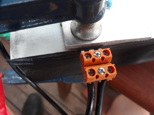 Cheers Caveman Mark Off grid eastern Melb |
||||
| renewableMark Guru Joined: 09/12/2017 Location: AustraliaPosts: 1678 |
10 done now and range from 214 to 216 Cheers Caveman Mark Off grid eastern Melb |
||||
| renewableMark Guru Joined: 09/12/2017 Location: AustraliaPosts: 1678 |
got 30 done now, funny thingis most are measuring a small voltage of around 10-11mv, but some are much higher like 78.4 and .367A. It still has the similar ratio of around 214, but the overall readings for both voltage and amps are higher. I went back and did the same tests on the numbered fets after the resistors cooled down. The numbers were different, but the ratios still the same. HA I might just be learning after all!! Cheers Caveman Mark Off grid eastern Melb |
||||
| Warpspeed Guru Joined: 09/08/2007 Location: AustraliaPosts: 4406 |
Mark, when you drop in tomorrow, bring a few of those mosfets with you. Cheers, �Tony. |
||||
| Tinker Guru Joined: 07/11/2007 Location: AustraliaPosts: 1904 |
Yes, there is a learning curve with everything in regard to these inverters. It would be very helpful if you quoted what you were measuring, like is it Amps, Volts Millivolts Watts etc etc.. Just typing the figure you see on your meter gets everybody who reads your post guessing which meter you were looking at. Anyway, you have lots of testing power available from your battery bank but seem to be using too little of it. There should be a circuit like: + supply(battery) - 10A meter - Heatsink drain connection. The return should be source terminal - big water cooled resistor - negative supply. In that circuit your meter should be reading close to 10A when you apply 12V to the gate (negative is common). You might have to mess with different resistors until you get a decent current to flow. This is easy for me with an adjustable power supply but you should be able to get close to 10A with your battery. It is *really* important to have a decent test current through the mosfet. But be careful, your meter internal fuse will blow if you get that resistor too small (Ohms). Once you get that going have a go measuring the millivolts between the drain and source legs. One step at a time will get you there. Now, the millivolt reading divided by the current on your Amp meter will give you the RDSon of the mosfet. Take care about the decimal places with this calculation. But, since you are matching Mosfets the actual RDSon is only academic, nice to know. What I do is write the millivolts on the back of each mosfet with pencil. You then have a figure to compare with, so, select 6 off with a similar reading for one inverter leg, ditto for the other legs. It little matters if the reading between the leg groups are somewhat different, what you are aiming for is selecting those in parallel to have a RDSon as closely matched as possible. This way they will share the load equally. Keep at it  Klaus |
||||
| renewableMark Guru Joined: 09/12/2017 Location: AustraliaPosts: 1678 |
@ Tony, thanks for looking at my stuffed caravan solar controller, I'll bring some fets with me for you to look at. Cheers @ Klaus, mate most of the tests were very consistent, I was pleased, however the results were lower than Mad was getting, at least they are consistent. Such as Fet 1 .048A 10.3mv Fet 2 .048A 10.3mv Fet 3 .047A 10.1mv Fet 4 .060 12.8mv Cheers Caveman Mark Off grid eastern Melb |
||||
| renewableMark Guru Joined: 09/12/2017 Location: AustraliaPosts: 1678 |
And seriously, thanks again fellas, you have all been a big help. Not if, but when, this inverter is running nicely, it will be due to the efforts of you buggers. Thanks, I do appreciate it. Cheers Caveman Mark Off grid eastern Melb |
||||
| Madness Guru Joined: 08/10/2011 Location: AustraliaPosts: 2498 |
Something is not right there Mark, that results in >200 milliohms should be around 2.7 milliohms. There are only 10 types of people in the world: those who understand binary, and those who don't. |
||||
