
|
|
Forum Index : Electronics : 6Kw Ozinverter build
| Author | Message | ||||
| Tinker Guru Joined: 07/11/2007 Location: AustraliaPosts: 1904 |
Yes, I think he is reading his Ampmeter wrong. 48 milli Amps is ridiculous, there should be at least 4.8 AMPS. Closer to 10 AMPS is even better but that might not be obtainable with a limited series resistor choice. Mark, if you have an old bar heater element you might reuse some of the resistor wire (nichrome)these elements are wound with. The thicker the wire the better. You would need the inner part from a terminal block to connect (can't solder it) and the terminal's plastic would melt. The more you experiment with basics, like making resistors and see what effect that has to the current flowing through it, the easier the electricity mystery will come into focus. Klaus |
||||
| tinyt Guru Joined: 12/11/2017 Location: United StatesPosts: 431 |
I am trying to figure this out: 4x20ah 12v in series = 4 x 12 = 48V 2x20w 33r resistors in parallel = 33/2 = 16.5 ohms I assume that the connection for measuring current is batteries(positive terminal) + ammeter + resistors + mosfet + batteries(negative terminal). 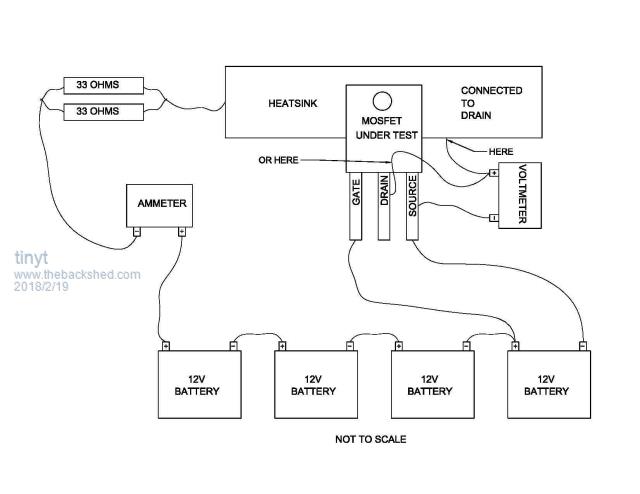 If the mosfet is dead short, there will be maximum current of 48/16.5 = 2.91 amps If the mosfet is 'bad'. For example, there is a voltage drop of let us say 1 volt across the mosfet drain to source , the ammeter will read (48-1)/16.5 = about 2.84 amps. Then the RDSon of this mosfet is about 1V/2.84 amps = .352 ohms or 320 milliohms. I don't know what meters are being use, if the connection is what I described above. maybe there is too much voltage drop in the ammeter or between mosfet drain and the heatsink. Or maybe the mosfet is not being gated on (+ 12 volts with reference to mosfet source/battery negative) |
||||
| Warpspeed Guru Joined: 09/08/2007 Location: AustraliaPosts: 4406 |
Mark, something is very wrong with your figures. Anyhow I will give you a demo of how I do it. Cheers, �Tony. |
||||
renewableMark Guru Joined: 09/12/2017 Location: AustraliaPosts: 1678 |
Oh jeez I'm a goose, I had the ammeter across the legs, not in series. What a prawn, that's so silly it's embarrassing.  Thanks Tinyt, that drawing is correct except my ammeter was in the same position as the voltmeter. Thanks everyone. Cheers Caveman Mark Off grid eastern Melb |
||||
| Tinker Guru Joined: 07/11/2007 Location: AustraliaPosts: 1904 |
Mark, in that drawing the (milli)Volt meter should only connect where you marked "or here". And do use test probes (the ones that came with the meter), placed on the drain & source leg, as close as possible against the Mosfet body, despite what mad mentioned about probes. How about testing the millivolts with the probe tips and also with the alligator clips? If there is no difference I stand corrected. Klaus |
||||
| renewableMark Guru Joined: 09/12/2017 Location: AustraliaPosts: 1678 |
Thanks Tinker, that's how Warp showed me today. I'm sure Mad's way would work too with the right croc clips, most stuff these days is such flimsy crap though. Thanks to Warpspeed for the demo today, very impressive shed you have there. That inverter looks bloody fantastic, you should do kits for it, that ease of replacement parts is very well thought out, good work mate. Cheers Caveman Mark Off grid eastern Melb |
||||
| Warpspeed Guru Joined: 09/08/2007 Location: AustraliaPosts: 4406 |
Its one of Murphy's laws. If its very easy to replace and you have spares, it will never fail. Its always the most inaccessible and difficult to reach part that is unreliable. Cheers, �Tony. |
||||
| renewableMark Guru Joined: 09/12/2017 Location: AustraliaPosts: 1678 |
OK boys, had another crack at the fet testing Still using 48v bank, did the wiring as per TinyT's diagram. Only change is I used more resisters 4x 10ohm in parallel then in series with another lot of 4 in parallel giving me 9.6 odd amps. So @ 48v I am getting 28.7mv @9.58A I have done 8 so far and all look similar. Do those figures look right? Cheers Caveman Mark Off grid eastern Melb |
||||
| Warpspeed Guru Joined: 09/08/2007 Location: AustraliaPosts: 4406 |
Sounds about right. 28.7mV divided by 9.58 = 2.995 milliohms. Cheers, �Tony. |
||||
| renewableMark Guru Joined: 09/12/2017 Location: AustraliaPosts: 1678 |
Thanks mate, I checked the data sheet here And is has typ 2.9 max 3.5 m ohms Cheers Caveman Mark Off grid eastern Melb |
||||
| Warpspeed Guru Joined: 09/08/2007 Location: AustraliaPosts: 4406 |
It does vary a bit with the batch, and from manufacturer to manufacturer. Three milliohms is right in the middle of what you might expect. As long as they are all pretty much the same you are set to go. Cheers, �Tony. |
||||
| renewableMark Guru Joined: 09/12/2017 Location: AustraliaPosts: 1678 |
All done, there are quite a few that are 2.76,2.74 prob half, the remainder are 2.84,2.83,2.80 It's actually very quick if you set it up right. Thanks for the help guys. Cheers Caveman Mark Off grid eastern Melb |
||||
| Tinker Guru Joined: 07/11/2007 Location: AustraliaPosts: 1904 |
Good that you have worked it out at last. Using 9.58 amps paid off too, at this current a bad connection is unlikely and you were giving the drain/source junction a good test. Now you might grasp why I use 10amps, that current gives a direct m Ohm reading on the m V meter if you move the decimal point one place to the left  . .Anyway, you seem to have a decent batch of Mosfets there. Well done! Klaus |
||||
| renewableMark Guru Joined: 09/12/2017 Location: AustraliaPosts: 1678 |
Thanks Klaus, glad to have that done. Those resistors were less than $10, so well worth the effort to get the amps up. Amazing how warm the water in the bucket was after they were all done, and each one was only on for 5 sec at most. Cheers Caveman Mark Off grid eastern Melb |
||||
| renewableMark Guru Joined: 09/12/2017 Location: AustraliaPosts: 1678 |
Got to the heatsink part. I was going to use the compound mitre saw, but the blades were $90 for a metal one, and probably won't use it again, so went with the scumbag option. After stuffing around I really wish I just got the metal blade for the saw. The cross cut worked out really well, but cutting the fins was a bit of a bugger. They need a bit of cleaning up and getting rid of any loose bits, might pressure wash it after filing. 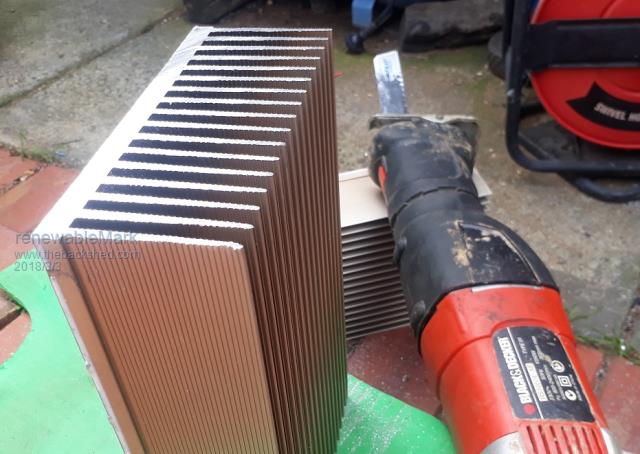 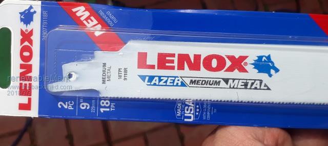 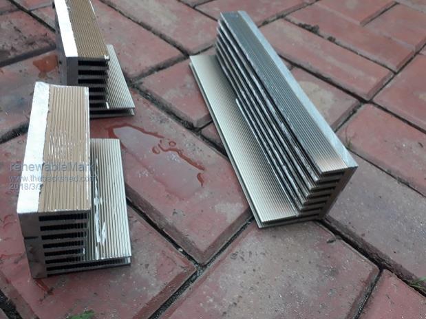 Cheers Caveman Mark Off grid eastern Melb |
||||
| Warpspeed Guru Joined: 09/08/2007 Location: AustraliaPosts: 4406 |
A rotary wire brush in an electric drill will remove all of the "fluff" and leave a smooth burnished finish. Cheers, �Tony. |
||||
| Tinker Guru Joined: 07/11/2007 Location: AustraliaPosts: 1904 |
I don't understand you guys. You have a beautiful heatink, big enough to cool the inverter without the fan running 95% of the time. Then you go and butcher a lot of the fin area off  . .So you end up having to install a big fan or two and have it running a lot. Beats me... Klaus |
||||
| renewableMark Guru Joined: 09/12/2017 Location: AustraliaPosts: 1678 |
I'm limited with the design of the board, the heatsink has to fit around the capacitors. Mad reckons his fans never get to full speed, Oz likes keeping the caps cool with airflow, if the fans only take a couple of watts then no big deal. With all the offcuts and extra bits I'll have I did think of bolting on more heatsink to the backs of the fitted ones. Haven't got that far yet. Cheers Caveman Mark Off grid eastern Melb |
||||
Madness Guru Joined: 08/10/2011 Location: AustraliaPosts: 2498 |
That is right they don't get to full speed but they are big 140mm fans, also I have mine setup so natural convection helps the cooling. I have the fan speed controller set so a few degrees above normal running the fans startup. This the empty case as it hangs on the wall. 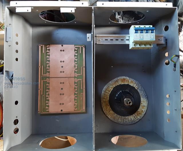 Tinker Mark is following the original Oztules design, he does not have the experience to go out on a limb with a one-off design. There are only 10 types of people in the world: those who understand binary, and those who don't. |
||||
| Tinker Guru Joined: 07/11/2007 Location: AustraliaPosts: 1904 |
Is it not possible to fit the capacitors on the other side of the PCB? They do have plated thru holes, have they not. This idea certainly works for me, allowing untrimmed heatsinks to fit on the the PCB. The caps are kept cooler there, away from the hot heatsink fins, in the bargain. Or did this idea not occur to the followers of the original oztules design? Interesting to see all the work involved in fitting two Aerosharp enclosures together to gain more space. Making a new enclosure from scratch would be just as much work but with the big advantage of having *no* size restrictions and the choice to mount parts so they connect easier with others in the enclosure. I'm just assembling my 3+ KW inverter, might take some detailed pics to show what I'm getting on about. Klaus |
||||
