Notice. New forum software under development. It's going to miss a few functions and look a bit ugly for a while, but I'm working on it full time now as the old forum was too unstable. Couple days, all good. If you notice any issues, please contact me.
wiseguy Guru Joined: 21/06/2018 Location: AustraliaPosts: 1000
Posted: 04:52am 23 Oct 2018
Copy link to clipboard
Print this post
Mark - I promise we wont hijack your thread much more.
Warp, Im still having trouble with this - the only source of current is from the battery. If the top transistor for the half bridge is only on for half the time then for 125A rms the peak current must be higher than that not lower - maybe I am missing something and you still need to try harder with me.... exercising the grey matter from time to time is good.If at first you dont succeed, I suggest you avoid sky diving.... Cheers Mike
renewableMark Guru Joined: 09/12/2017 Location: AustraliaPosts: 1678
Posted: 05:32am 23 Oct 2018
Copy link to clipboard
Print this post
I don't care, after the first build was done it's been a kind of chat boardCheers Caveman Mark Off grid eastern Melb
renewableMark Guru Joined: 09/12/2017 Location: AustraliaPosts: 1678
Posted: 05:46am 23 Oct 2018
Copy link to clipboard
Print this post
Puzzled about that, don't recall anyone getting pissed about maths here.Cheers Caveman Mark Off grid eastern Melb
johnmc Senior Member Joined: 21/01/2011 Location: AustraliaPosts: 282
Posted: 06:49am 23 Oct 2018
Copy link to clipboard
Print this post
Thanks Warpspeed ,grey matter needs a workout, as they say use it or loose it.
cheers john johnmc
Madness Guru Joined: 08/10/2011 Location: AustraliaPosts: 2498
Posted: 07:08am 23 Oct 2018
Copy link to clipboard
Print this post
There is also times where something starting up will increase the current by many times these figures. Also it is not unreasonable to expect loads over 6KW for a few minutes. There are only 10 types of people in the world: those who understand binary, and those who don't.
Warpspeed Guru Joined: 09/08/2007 Location: AustraliaPosts: 4406
Posted: 07:11am 23 Oct 2018
Copy link to clipboard
Print this post
Its still 125 amps rms flowing through the load, first in one direction, then in the opposite direction (because its ac).
In one direction it will flow through the upper mosfet on one side of the bridge, through the primary, then through the lower mosfet on the opposite side of the bridge. Those two diagonal mosfets each see 125 amps rms for one half cycle.
During the second half cycle the current direction changes to the opposite diagonal pair of mosfets, and the current through the primary reverses.
Each diagonal pair conducts for each half cycle, then they get turned off for the following half cycle. Each individual mosfet only works for half the total time.
Nowhere does the current double. Its always 125 amps rms but it gets steered through a different pair of mosfets each half cycle.
Because each mosfet in the bridge gets a total complete rest with zero load for half the time, it has to work only half as hard. Cheers, �Tony.
Warpspeed Guru Joined: 09/08/2007 Location: AustraliaPosts: 4406
Posted: 07:27am 23 Oct 2018
Copy link to clipboard
Print this post
Give it a rest Madness.
The problem is only temperature rise, which is how we rate the current carrying capacity through just about anything.
Something really fragile like a fuse or a mosfet will go pop very quickly under overload conditions because it has a very small thermal mass.
Something with more thermal mass like cable, or a plug and socket or a brass terminal block or a transformer will withstand massive short term overloads just fine because the temperature rise will be much slower.
You don't like screw terminal blocks, thats fine, don't use them.
All your normal career electrical sparky ever sees in his trade working on mains power distribution every day, are screw terminal blocks and crimp connectors. None of the switches, power outlets or light fittings in your house are soldered.
Maybe all the screws are going to suddenly go loose fall out and burn your house down. Perhaps you should be very afraid.... Cheers, �Tony.
Madness Guru Joined: 08/10/2011 Location: AustraliaPosts: 2498
Posted: 08:23am 23 Oct 2018
Copy link to clipboard
Print this post
Some people don't like it when someone disagrees with them don't they?
There are only 10 types of people in the world: those who understand binary, and those who don't.
renewableMark Guru Joined: 09/12/2017 Location: AustraliaPosts: 1678
Posted: 08:54am 23 Oct 2018
Copy link to clipboard
Print this post
Fk I wish you two would get along.
Warp I too have the concern of screw terminals going loose.
And yes I have seen it, years ago I did a job in someones house, the next day she complained how her light in the hall didn't work, and as I was in the roof in that area it must have been me that caused it. Anyway I went up in the roof to where I was and couldn't find anything out of the ordinary, there was wiring etc that I would have bumped etc but didn't mess with anything.
So I got down turned the power off and looked at the light switch, it was loose as fk, tightened it up turned the mains on and all sweet. The lady was a mech engineer and she couldn't explain why it happened any better than I could, but she witnessed the whole thing.Cheers Caveman Mark Off grid eastern Melb
renewableMark Guru Joined: 09/12/2017 Location: AustraliaPosts: 1678
Posted: 09:00am 23 Oct 2018
Copy link to clipboard
Print this post
If those terminals were 40A with spring washers they would be more trusted for a high power inverter application. I really doubt the makers of those units would recommend them for what we want to do to them. Might be wrong.....dunno.Cheers Caveman Mark Off grid eastern Melb
Ralph2k6 Senior Member Joined: 24/09/2017 Location: AustraliaPosts: 129
Posted: 10:50am 23 Oct 2018
Copy link to clipboard
Print this post
2c
Tiny bit of non hardening goop (can't remember name, aero something?) on the screw heads can help prevent the terminal loosening. Often see it, like a loctite but exposed to the air. Also as we all know, not uncommon for copper under srews to soften(aka shift a smidge) through thermal cycling.
Ps lovely work there Mark. Got a Madness 'kit' but not had a chance to get it underway Edited by Ralph2k6 2018-10-24Ralph
wiseguy Guru Joined: 21/06/2018 Location: AustraliaPosts: 1000
Posted: 01:36pm 23 Oct 2018
Copy link to clipboard
Print this post
Warp dont lose it with me - I thought perhaps a picture will either help me see what you mean or vice versa.
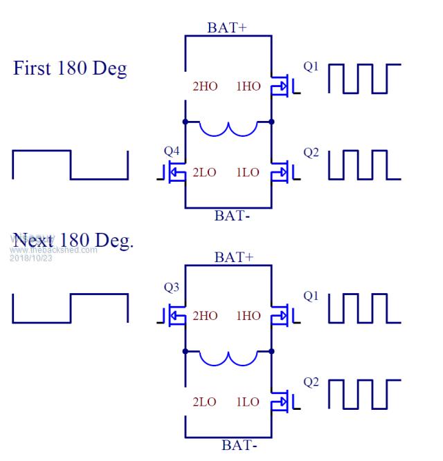
The 2 humps between the legs of the "H" are the toroid primary - with no choke...
For the first 180 degrees the only path for Battery current to the inverter circuit is via Q1. (Q3 is off)
For the next 180 degrees the only path for Battery current to the inverter circuit is via Q2. (Q4 is off)
As Q1 is switching in the first 180 whilst supplying inverter current, likewise Q2 is switching for the next 180 supplying inverter current, for a 125A rms total current means that the current must increase beyond 125A to compensate for the current that is not flowing during the off time.
eg for a 50% HF (24kHz) duty cycle, Q1 passes 125 x 1/d = 250A peak (125A rms)180deg. & for a 50% HF (24kHz) duty cycle, Q2 passes 125 x 1/d = 250A peak (125A rms)180deg.
Maybe you can see now why my mind is having trouble accepting otherwise. In real life I also get that Q1 & Q2 are modulated with a varying pwm to generate the 50Hz component so the 50% duty cycle is only part of that total waveform.
The picture in my mind says the total of the first 180 deg & the second 180 deg is 125A rms? But a much higher peak current is happening in the Q1 & Q2 FETs.
Even at max duty cycle continuous, the peak current will be slightly higher than 125A to compensate for the current that doesn't flow during the selected dead time?
I understand AC and how it is derived from the waveforms - I am reducing the issue though to a simpler series circuit for analysis. I can concede that 125ARMS is flowing through the transformer primary but just not where it comes from and in what amount :)
Edited by wiseguy 2018-10-25If at first you dont succeed, I suggest you avoid sky diving.... Cheers Mike
tinyt Guru Joined: 12/11/2017 Location: United StatesPosts: 431
Posted: 02:33pm 23 Oct 2018
Copy link to clipboard
Print this post
I am confused by the above and the picture. Maybe: via Q4 (Q1). (Q3 is off) via Q3 (Q2). (Q4 is off)
wiseguy Guru Joined: 21/06/2018 Location: AustraliaPosts: 1000
Posted: 02:48pm 23 Oct 2018
Copy link to clipboard
Print this post
Sorry for any confusion I caused.
During the first 10mSecs Q4 is turned on & remains on. Then simultaneously PWM is applied to Q1 & Q2 to produce 180 degrees of half the sinewave through the primary & Q4. Then Q3 is turned on and remains on whilst Q1 & Q2 are again modulated with the inverse pwm through the primary to Q3 to create the next 180 degrees & other half of the sinewave.
But the only path to the battery (+) is via Q1 during the first half and to the battery (-) via Q2 for the second half.
I left out of the picture the mosfet that is off as it is clearer where the current is flowing. ( well to me anyway.....)Edited by wiseguy 2018-10-25If at first you dont succeed, I suggest you avoid sky diving.... Cheers Mike
Warpspeed Guru Joined: 09/08/2007 Location: AustraliaPosts: 4406
Posted: 09:33pm 23 Oct 2018
Copy link to clipboard
Print this post
There are many different ways to PWM something to generate an ac waveform in the load, unipolar, bipolar, and various different PWM drive waveforms.
But over one full 20mS period every individual mosfet averages out having a 50% duty cycle no matter how the actual switching patter is arranged.
Lets stick with our loved/hated EG driver boards and chips for now.
We have one side of the bridge switched with a 50Hz square wave, and the other side switched with 23Khz PWM to produce a sinusoidal "hump" to generate one half of a mains cycle.
Using your top diagram for the first 180 degrees, Q4 will be hard on for the first half of the cycle. We can really ignore that, as its hard on all the time for just the first half of the cycle under discussion.
Q1 and Q2 will be PWM'd to produce a half sinusoidal voltage and current "hump". Q1 does all the switching work, and controls the power switched from the +ve battery source. Q1 will start out with a very low duty cycle beginning at the zero crossing point beginning of this hump, rising up to a much larger duty cycle right at the peak of the hump, then the duty cycle gradually falls back down to zero on the other side.
So lets look at how Q1 and Q2 behave over one PWM cycle at 23Khz. We can forget about Q4 its just hard on all the time and out of the picture.
So Q1 turns on and current flows in a series circuit through Q1, through the transformer primary, through the series choke, and to ground through Q4.
Current through the primary cannot rise instantly because of the inductance of the series choke, current ramps up very slightly though, to be very slightly higher.
When Q1 turns off, current continues to flow through the primary of the transformer from the energy stored in the choke, but cannot fall instantly because of the inductance of the series choke, it ramps down very slightly, to be very slightly lower.
The interesting thing here is that there is no requirement to turn on Q2 when Q1 turns off. Current through the choke will flow through the internal diode in Q2 even if the gate voltage of Q2 is never turned on. This actually occurs during dead time.
We do however wish to turn Q2 on because the RDSon voltage drop across Q2 will be much lower than if we just use its internal diode to carry the off current. Anyhow Q2 carries the stored energy in the series choke that continues to feed current through the primary while Q1 is off.
At the crest of the hump, the current through both choke and primary will rise to around 176.75 amps if the rms value in the primary is 125 amps.
Its the series choke that averages out the high frequency PWM switching so that the current through the primary is a nice clean sinusoidal 10mS wide current hump.
The current through both Q1 and Q2 will be 125 amps rms and 177 amps peak over the half cycle hump over which they work.
Q4 does nothing, but still sees a smooth 50Hz current hump the same as Q1 and Q2 sees. Everything is in series so the current waveform is the same everywhere.
If there is no choke fitted and the transformer were perfect with zero leakage inductance an efficient ferrite core and zero capacitance and an infinitely high self resonance, you should see a perfect 23Khz PWM waveform reproduced across the secondary at higher voltage, which is not really what we want.
Current through the 6Kw resistive load would reach the same peak value of voltage and current during each PWM on period, even at low duty cycle ! and zero during each off period of the pwm, just exactly as I think Wiseguy is visualizing.
What would actually be happening would be that a 177 amp rectangular wave current would be switching on and off through the primary, through the secondary, and through the load at 23 Khz. We will never see a 50Hz sine wave anywhere, just high frequency PWM with 340 volts peak to peak coming out of the inverter.
It all gets even worse if there is any shunt capacitance involved as there certainly will be with any practical transformer. Its probable instant death to the mosfets as the instantaneous current spikes charging and discharging that stray capacitance at 23Khz at high voltage in the secondary would be virtually unlimited.
So we absolutely must have some series inductance in the primary. If you run it without a choke, the transformer itself will have some leakage inductance, but its never going to be enough for the circuit to work as it should, your mosfets are going to be very highly stressed.
That is why we need a choke.
All this really high stress stuff is still in play even with no load on the inverter. Pretty early on someone (oZ ?) discovered a few turns on a lump of ferrite would dramatically lower the idle current. He was on the right track !! Reducing those killer current spikes will be hugely beneficial even at zero load.
But doing it properly requires a series choke that still continues to work right up to full rated maximum power and beyond, for safe efficient operation.
Its the choke that turns a high frequency PWM hard switched voltage from the bridge into a nice clean 50Hz half sine wave hump current to drive the transformer. That is what it is there for, and that is what it does.
If there is no choke, the transformer will also try to do that by default, but very inefficiently, and with a lot more heat generated everywhere. Skin effect in the wire, eddy currents in the core and it will place very high extra stresses on the mosfets which will almost be on fire from from higher peak currents.
Much better to avoid all thet strife with a proper choke. Edited by Warpspeed 2018-10-25Cheers, �Tony.
wiseguy Guru Joined: 21/06/2018 Location: AustraliaPosts: 1000
Posted: 10:39pm 23 Oct 2018
Copy link to clipboard
Print this post
Sometimes in trying to make something simpler we end up making it more complicated.
The choke was left out in my simple visualisation picture as it complicated what I was trying to get across - I know the value of the choke and will certainly have one.
I was trying to show that the current path from the battery can only be via Q1 for 10mS & Q2 for 10mS during each alternate half cycle. The fact that they are switching and have an off time proves that for 125A rms from the battery more than 125A peak current flows through them to compensate for the off time.
For a 50% duty cycle the current is doubled but for the sinusoid yes its a .7071 increase to 177A.
I feel we are making progress and have established that it is certainly more than 62.5A.
I think we are now on the same page and that 177A flows through Q1 and then Q2 so when we apportion the peak current shared between FETs and connectors to the PCB it is a big spike of current more than the RMS value and for I squared V calcs important.Thanks for a lively discussion. Edited by wiseguy 2018-10-25If at first you dont succeed, I suggest you avoid sky diving.... Cheers Mike
Warpspeed Guru Joined: 09/08/2007 Location: AustraliaPosts: 4406
Posted: 11:32pm 23 Oct 2018
Copy link to clipboard
Print this post
Yes it has definitely been an interesting discussion, and an excellent opportunity to revise some very old theory.
Your original thoughts are all perfectly valid if this was a bridge type of forward converter, and fitted with a transformer suitable for transmitting 23Khz PWM efficiently. That type of supply also requires a choke, but its on the secondary side after the rectifier.
At first I just assumed we were discussing a PWM type of sine wave inverter, which always must have a primary choke, a low frequency type of transformer, and is an entirely different beast with a very different mode of operation.
It was only while thinking this through I very slowly began to realize we were thinking about very different applications.
With the current averaging choke in the primary we have 177 amps peak, 125 amps rms, but only for half the total period. So the time averaged current would be 62.5 amps.
But for calculating resistive losses and dissipated power, we need the rms value not the average value, and that will be around 88 amps per mosfet leg.
Without an averaging choke in the primary its all very different.
Edited by Warpspeed 2018-10-25Cheers, �Tony.
wiseguy Guru Joined: 21/06/2018 Location: AustraliaPosts: 1000
Posted: 06:03am 24 Oct 2018
Copy link to clipboard
Print this post
Crap & we were doing so well there for a while haha
I have only ever been talking about the PWM of the Oz inverter topology internals. Although 24kHz is used for modulation I never intended to transform it only the resultant 50Hz. My drawing is how the OZ inverter with an EG8010 works. OK so we are on the same page but opposite sides lol - lets leave it there ........
Maybe I need to improve my technical communication skills. Edited by wiseguy 2018-10-25If at first you dont succeed, I suggest you avoid sky diving.... Cheers Mike
wiseguy Guru Joined: 21/06/2018 Location: AustraliaPosts: 1000
Posted: 09:24am 24 Oct 2018
Copy link to clipboard
Print this post
Just for interest I decided to check the power loss for 15mm long legs of a single HY4008 Mosfet with some back of the envelope calcs..
I worked out the legs are around 0.76 sq mm or 500uOhms for 15mm.
At 100Arms each leg dissipates ~ 4W or ~ 8 W for 1 FET, It looks bad initially but when shared between 4 fets it then drops to ~0.3W per leg or 0.6W per FET.
So soldering them into the PCB at the fat part may save ~ 10W (@ 5KW) maybe not a big gain but a gain nevertheless.
Makes you wonder why they make the gate lead so huge - some of that copper would be better in the other 2 legs......
Probably useless information for mostIf at first you dont succeed, I suggest you avoid sky diving.... Cheers Mike
renewableMark Guru Joined: 09/12/2017 Location: AustraliaPosts: 1678
Posted: 07:15am 27 Oct 2018
Copy link to clipboard
Print this post
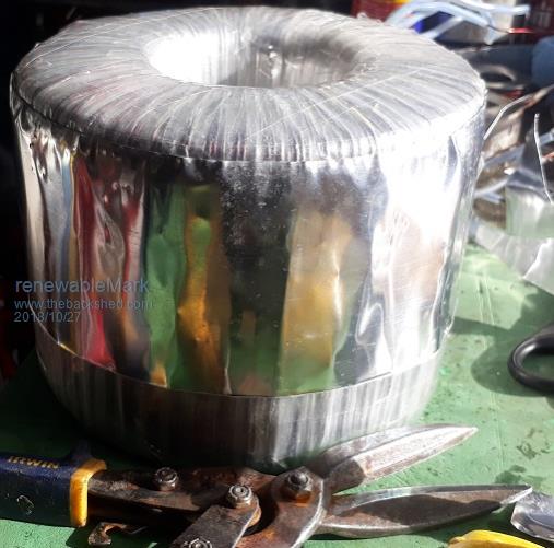
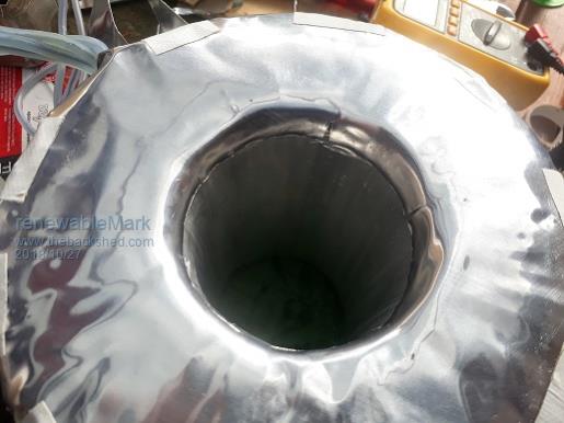
OK toroid is done with the 4 secondaries. Next I wanted to try a method to create a shield between the secondaries and the primary. So after the last secondary was wound I wrapped 3 layers of mylar over it. Then got 65 thickness extra strong packing tape and went all around it, through the centre in small strips and on the ends to make sure there was no chance of a short anywhere. Then got some al flashing and put a band around the outside.
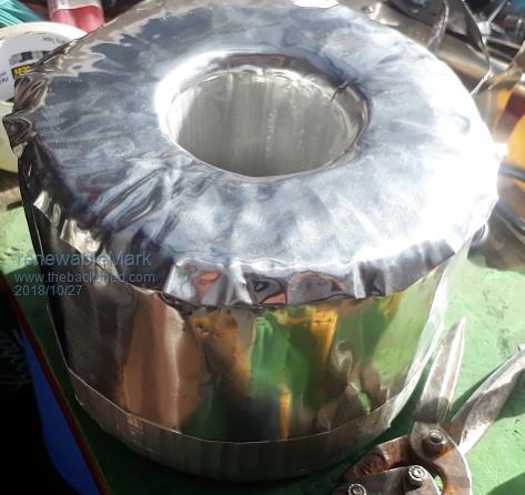
Then cut a circle for the end and put that in place.
Taped it down and pushed the edges down.
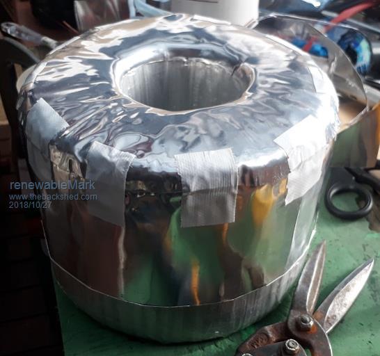
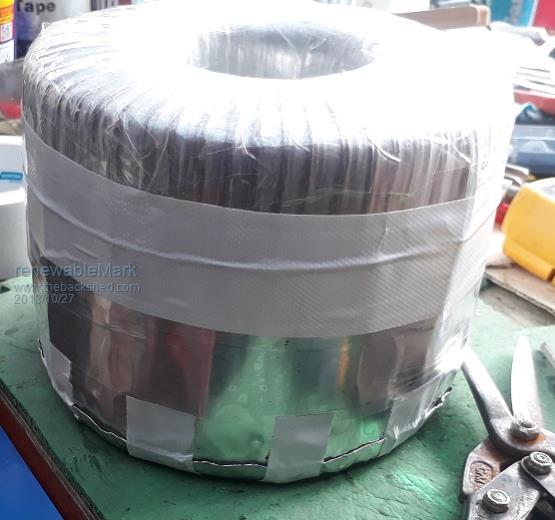
Then taped the band with a few layers of clear 65 thickness packing tape and another layer of cloth tape.
So the idea is to use kitchen foil on the inside, then make another top for the other side and another band so there is an unconnected overlap of 1 turn.
Any feedback before I go any further?
Edited by renewableMark 2018-10-28Cheers Caveman Mark Off grid eastern Melb