
|
|
Forum Index : Solar : HWC element powered from HV PV array
| Author | Message | ||||
| Solar Mike Guru Joined: 08/02/2015 Location: New ZealandPosts: 1124 |
10 of These 1000uf 450v in parallel may be ok. Looked up that "KMH" model data sheets and it doesn't exist, so it could be some re-branded anything. Same goes for These 4700uf 450v, that black case gold text is pretty generic on a lot of the "HiFi" caps on EBay. |
||||
| Warpspeed Guru Joined: 09/08/2007 Location: AustraliaPosts: 4406 |
A working prototype can probably be first cobbled together with junk parts, and once everything is sorted out, something a bit better for both mosfets and capacitor. This has been running for a couple of hours now, and the 100 milliohm mosfet and capacitor are both stone cold. I don't think any of this is going to present an insurmountable problem. The whole thing is so simple even veroboard becomes feasible for a first time effort. Cheers, �Tony. |
||||
| Solar Mike Guru Joined: 08/02/2015 Location: New ZealandPosts: 1124 |
I have managed to get ten B43511 EPCOS 1500uf 450v caps from an old switch mode psu unit, tested them they seem ok, ripple rating is 14 amps @25c. Have designed a pcb to mount multiples of two, so can do some tests on various values. If I make all the pcbs < 100mm sq then they only cost 50c each. 200k resistance with led to show they are charged.. 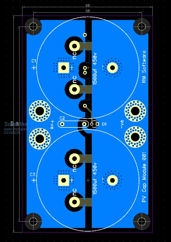 Mike |
||||
| Warpspeed Guru Joined: 09/08/2007 Location: AustraliaPosts: 4406 |
I had three 15,000uF 63v connected in parallel at one stage with a no load solar voltage of 40v. Had a little bit of an accidental short across that, created quite a bang. I wonder if fusing the capacitors individually might be worth doing ? Cheers, �Tony. |
||||
| davef Guru Joined: 14/05/2006 Location: New ZealandPosts: 499 |
Warpspeed, Does your implementation start up cleanly as the panel voltage goes from 0 Volts to say 15-20 Volts? |
||||
| Warpspeed Guru Joined: 09/08/2007 Location: AustraliaPosts: 4406 |
Its should, because all gate drive is cut until the supply voltage to the driver reaches around 11 volts. The specification is rather wide, but the extremes are 9v and 13.5v Still nothing will happen until the main capacitor reaches the upper threshold voltage. At that point the mosfet turns on hard and dumps a packet of energy into the load. Haven't actually tested it, but its very similar to many related circuits that have all worked for me in the past, under similar operating conditions, so I don't expect any problems. Its a pretty simple circuit with few surprises. Cheers, �Tony. |
||||
| davef Guru Joined: 14/05/2006 Location: New ZealandPosts: 499 |
I am thinking more about how the NE555 switching responds to the ramp-up and down of its supply voltage. I had an issue with my unit not behaving: here If the NE555 can handle that then I'll dig one out and try it. Would be nice to get rid of the aux 13V5 supply in my unit. Cheers, Dave |
||||
| Tinker Guru Joined: 07/11/2007 Location: AustraliaPosts: 1904 |
Good idea Tony, that would be very useful here since I do have an instant gas HWS (no pilot light) that does all the water heating I require. I also have a stack of hi Voltage caps (470uF/450V) out of used Areosharp boards, 20 of these in parallel might do the trick. Ah, another project - no end to these on this forum  . .Klaus |
||||
| Davo99 Guru Joined: 03/06/2019 Location: AustraliaPosts: 1577 |
Sounds excellent Tony. Your room heating is a great idea. We have an ensuite on the shade side of the house that we don't use much becuse it's too bloody cold in there. Slab floor radiates cold even into the bedroom. The door is kept closed for that reason. In summer, being on the western side and with Floor to ceiling windows, the bathroom and dressing room are hot boxes and you still can't get in there and then they radiate heat. Terribly designed area and I'm going to look at some shade blinds before this summer hits. Having some passive heating in there would be a BIG bonus in winter. Although it is on the south side, I have noticed that roof although angled away still gets some Sun. Pretty useless for panels on a GTI but I could easy put 4 KW worth of old 190's or something and if that gave 4 Kwh a day of heat in there it would be a bonus and make something worthwhile out of otherwise wasted roof space and obsolete panels. This controller would also be very useful in low voltage mode for greenhouse heating which was the original idea before I saw the potential for domestic HWS. I have a 100L tank in my little play greenhouse to store the heat and radiate it out at night. I have put a timer on it and am running a cheap 1800W Cup water boiler thing atm and the plants are going great guns. I put some lavender Clippings in there about 2 weeks ago and I noticed today they are getting little buds already. Put in about 200 Hedge cuttings and they are taking off as has everything else. So far we have only had 2 frosts this year but I think the water storage that keeps the greenhouse at 12oC or better on the coldest mornings is working really well. If it were possible to stack say 4 lower wattage and otherwise fairly useless 170W panels in parallel to really get some heat in the tank, that would be perfect. Would all be automatic and could be put anywhere without the need for AC power. I'm Thinking of going another way with this as well. An old Fridge with say a 20L plastic water tank in the bottom as being so well insulated it shouldn't take much heat storage to keep the thing warm. Could also Run an LED Light or light bar at the same time to provide Light during the day...... Or make up a devise that automatically opens and closes the door. :0) Thanks again everyone for the time and effort you are putting into this and sharing it with us plebs. |
||||
| Warpspeed Guru Joined: 09/08/2007 Location: AustraliaPosts: 4406 |
The dc supply to the 555 and gate driver need to be voltage regulated, or at least reach the voltage regulated condition when the under voltage lockout on the gate driver allows all the fun to commence. The dc on the main big electrolytic ramps up and down, but the control system must be voltage regulated for this to work. The 555 is really nice to use for this, because if its supplied with a regulated dc voltage, then the two switching thresholds are very clearly defined. If you use a comparator or an op amp in the usual Schmidt trigger configuration, working out all the interdependent standard resistor values becomes rather tricky. With a 555, we only need to figure out the values for two quite independent voltage dividers, and that is very straightforward. The low threshold is reached when pin 2 (trigger) falls below one third of the dc supply. High threshold is reached when pin 6 (threshold) reaches two thirds of the dc supply. There are on line resistor calculators that will find you the closest pair of standard resistor values for any voltage ratio you require. https://ns-electric.com/design-tools/resistor-calculator/ Cheers, �Tony. |
||||
| davef Guru Joined: 14/05/2006 Location: New ZealandPosts: 499 |
Agreed, trying to make a window detector with only three resistors and an op-amp was a bit tricky. Four resistors was a snap. Thanks for the link. Cheers, Dave |
||||
| Davo99 Guru Joined: 03/06/2019 Location: AustraliaPosts: 1577 |
Tony, is this the " final" circuit or do you need to do more testing/ modding on it? What sort of power would it handle with parallel panels? Is it just a case of the size of the mosfet or stacking them for the required capacity? I'm getting a bit lost with what everyone is doing here, would this circuit be suitable for driving a 240V /3600W element or is this for a 24V element? Would again the power handling capacity of this version just be dependent on the Mosfets used? I'm beyond primitive when it comes to this stuff but looking at the components, the connections and how many just go to ground, I may be in with a shot at this. Worst part might be turning up to jaycar like a complete Noob with a parts list saying I want this please. yeah I could buy a mixed bag but trying to read colour codes on Resistors drove me nuts years ago. Maybe I could cheat with a Multi meter?  |
||||
Ralph2k6 Senior Member Joined: 24/09/2017 Location: AustraliaPosts: 129 |
When you go into the store Dave, the resistors should be in little trays with values written on front. At home, I ALWAYS use a meter to check resistor values, just alot quicker for me. Edit: typo Ralph |
||||
| Warpspeed Guru Joined: 09/08/2007 Location: AustraliaPosts: 4406 |
Davo, If you can tell me exactly what you plan to do, I can then give more precise details. What type of heating load is it ? How many solar panels, what power are they rated for, and what is the maximum power voltage on the ratings plate ? Cheers, �Tony. |
||||
| Boppa Guru Joined: 08/11/2016 Location: AustraliaPosts: 814 |
Yup, they are almost invariably in the about 1mx1mx1.8m (measurements very approximate LOL) spinning storage unit, with hundreds of drawers in it, always with the value written on the front And yeah, I always use a multimeter to sort random resisters, much faster than trying to read the code (plus I'm red/green colour blind so red/yellow/orange can kinda blur together for me, especially since the colours tend to not always be the same shade if from different manufacturers) |
||||
| Davo99 Guru Joined: 03/06/2019 Location: AustraliaPosts: 1577 |
Resistance water heating. I would like ideally to use 240V 3600 or 4800W elements because I can source a free supply of those. Yes!  I would like to know/ learn enough to work with different configurations. I am thinking this should be straight forward by just changing some resistors..... By usually when I think something will be simple it's not. Ideally I would like to be able to throw enough power at a hot water tank to make it viable for domestic use, at least a Kw, 2 would be better. I would also like to be able to do a lower power setup say for a greenhouse. As for panels, does the size matter with the varying resistance or is the total KW the deciding factor? Lets say for the moment I can throw 18x 190W panels at the High power exercise. For the smaller setup, I will want to sink about 6Kwh into the tank for the greenhouse to get the energy storage I would like. To do that in winter I'm going to need about 2 Kw of panels to reliably generate that so lets call it 12 Panels. For the Fridge idea which will be much better insulated, I reckon 1 Kw for the light and heater ought to do it so 2 or 3 panels what ever suits best. I'm a little confused ( again) how this circuit will work. It's Pulsing the output from the panels which is accumulated in the caps to keep the panels at their peak power. More power, faster charge up, more frequent dump. I get that. Is the voltage critical or the amps Given the use of a mains rated element) or neither as the resistance of the element has now become redundant and the panels are able to work on the wattage generated independent of the Volts and amps? If this is the case, does the volt/amps of the panels matter as they would with direct connection or given the energy is being stored to a set point, it is only the amount of power from the panels that determines the Pulse time and therefore amount of watts applied to the element? I thought of this thread and circuit first thing this morning. Spoke too soon yesterday, had a decent frost this morning. Today I set up 4x 250W panels in an underplanted part of the garden and hooked them to the 1800W cup heater.I measured around 500W going to the element from Midday till around 2 Pm which surprised me and then the output dropped after that. If I can get near that 500W by 10 Am or so, I'll get a worthwhile amount of power in the tank but I'll get a whole lot more if I could bump that output to say 800W and hold it there longer. Thanks again for your time, effort and help with this. It's greatly appreciated and I know I'll learn a lot more and a lot faster by having something working I can make changes to and see the effect they have. |
||||
| Davo99 Guru Joined: 03/06/2019 Location: AustraliaPosts: 1577 |
|
||||
LadyN Guru Joined: 26/01/2019 Location: United StatesPosts: 408 |
My younger brother who just came back from base for this 4th July week gave us another idea. They use this little rice cooker to steam vegetables - and we both figured out it's a purely resistive element. There's a cutoff switch somewhere but if we emulate zero crossings, that should address the challenge, I think. These rice cookers use an interesting magnet + spring component that appears to have a temperature based behavior change. I am having a hard time locating how it works. The closest I got to was a discussion about curie points but its not clear whether that applies to the spring or the magnet, but that's perhaps another thread |
||||
| Warpspeed Guru Joined: 09/08/2007 Location: AustraliaPosts: 4406 |
O/k Davo, got the picture. The whole circuit will self adjust over a pretty wide range of conditions, but the various parts need to be selected to at least have some chance of working together. First thing is your heating element is in the 220v to 240v class, so this will need to be a high voltage system. We need a much lower constant regulated dc voltage to operate the electronic control system, probably +12v (or possibly +15v). The simplest and cheapest solution to that, will be the "guts" out of a standard 230v dc wall pack which are readily available on e-bay or Ali from China for a couple of dollars or so. Or you can buy a whole wall pack for about ten times the cost. 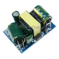 These are designed to work on any ac mains voltage anywhere in the world 80v to 265v, but in fact will run perfectly well from a dc supply up to around 400v max. When very lightly loaded they will start up and run from typically about 30v to 45v dc input. The output voltage will be close to being exactly 12.0v and it will be very well voltage regulated. The 12v supplies seem to be more commonly available right now, so lets assume we will be using a +12v dc supply for the control system. Now we need to decide on a solar panel configuration, which will require a series string of panels possibly six to eight 24v panels. There may be more than one series string required if there are a greater number of panels. We can connect series strings in parallel through high voltage diodes to get higher total current and power output. On each panel there will be a ratings sticker that will tell you the voltage at which maximum power is generated. It may say something like 200 watts at 31.6 volts. The power falls away at loaded voltages both higher and lower than that, and it falls away much faster at the higher voltage end. We select two voltage thresholds where the power has fallen by roughly equal amounts by testing one of the panels. If you are unable to do a practical power test, just assume suitable voltage thresholds might be 3v higher than the rated max power voltage, and 5v lower than the max rated power voltage for 24v panels. This will be pretty close. So for the hypothetical solar panels here, we assume 34.6v high threshold, and 26.6v low threshold. A rough as guts guess, might be that at 34.6v the power might have fallen by 10% below the peak. At 26.6v the power might also have fallen by 10% below the peak. If we can keep the voltage swinging back and forth over that range through peak power, we might estimate our overall power output at 95% of the peak rated power in a clear blue sky. If we had a series string of seven of these panels, the voltage thresholds of our control system need to be set at 34.6v x 7 = 242v for the high threshold, and 26.6v x 7 = 186v for the low threshold. Eight series connected panels would be 277v and 213v. Six series connected panels 208v and 160v. Its all good ! None of this is particularly critical, if its out by a few volts its going to make maybe 1% or 2% difference, so don't fret too much about all this. Its also possible to mix panels with slightly different max power voltages if the differences are not too large. But we need to know roughly where we are, to set up the voltage thresholds in the control system. Now we need to work out some suitable resistor values to get our 555 chip switching at the right threshold voltages. With a +12v dc supply, the upper threshold on pin 6 will be +8.0v, and the lower threshold on pin 2 will be +4.0v. (With a +15v dc supply it will be +10.0v and +5.0v) For the upper threshold we need a pair of resistors that will generate +8.0v from 242v. The upper resistor will have 234v across it, and the lower resistor 8.0v, that is a voltage ratio of 234/8 = 29.25 If we go to this web site: https://ns-electric.com/design-tools/resistor-calculator/ And scroll down to resistor ratio, and enter 29.25 We get 240K and 8.2K For the lower threshold we need resistor values to generate 4.0v from 186v. That is 182v across the upper resistor and 4.0v across the lower, a ratio of 45.5 And we get 910K and 20K The other parts we need to select are the main energy storage electrolytic, mosfets, heatsink, and transient voltage suppressor. More on this plus a schematic later. Cheers, �Tony. |
||||
| Davo99 Guru Joined: 03/06/2019 Location: AustraliaPosts: 1577 |
Thanks Tony. All easy to understand and within what I have played with before. I have 5 Of those little voltage regulators sitting on my desk in front of me right now. I saw them mentioned a few weeks back and thought something that can be hooked to a typical GTI level solar output and give a 12 V source would have to be very handy for Driving SSR's and other things so I ordered them and they arrived while I was away. The Little connection solder spots on them sure are small though! This is what I was talking about at the start. I have zero ability to design that circuit but I can easily get it and wire it to an SSR or other prebuilt Components to make something to perform the functions I want..... If the right components are available for the job. I have a bunch of different plugpacks up the back, I'll have to try hooking them to a couple of panels in series and see if they work. Would be satisfying to run all the ever growing power boards full of these chargers for the battery operated tools ( Even powerful chainsaws Now that work better than the petrol one) from some panels direct. I have a string of 8 185W panels along the roof of the back verandah with a long cable coming off them. These are what I use as a test array. I have found exactly what you have said, that the voltage variation caused by a load that is close enough makes little Difference. There is a fair amount of flexibility in the panels output but not an endless one. Particularly if the wattage is there, the voltage self regulates to quite an extent. the back of the house is also where all my orphan panels live. From memory I have 185, 240 and 175 Panels up there in 4 strings. Much is made about matching panels and making sure they are the same size, brand and even age but I think that it typical internet pedantic exaggeration. The arrays all run to the one twin tracker GTI. I have kept the Voltage close which means some different numbers of panels but I remember a 21V Difference between 2 Strings I paralleled. They have been playing together really well for about 4 months now and that inverter although double overclocked puts out great power. The panels face a couple of different directions and Pitch on same strings as well but again, they all seem to work with amazing efficiency for what they are, otherwise useless panels. I even have a couple of smaller panels paralleled on a string of larger panels so as not to pull down the whole array and that string works fine as I have kept an eye on that with an inline amp meter. The array on the shed is 9Kw going to a 5 Kw inverter. This array is 7.2 going to a 3.6Kw Inverter. For the last 6 weeks or so I have been taking an interest and recording, the 9 Kw array which faces north with matched 250w panels and the 7.2 array that faces west are nearly always within a KW of daily out put and often within half that. There are also days where the west array has done better than the north but I put that down to cloudy weather that fined up later in the afternoon. I bought 45 250W panels recently and only have 10 Up so far so I'll probably replace my orphan array which is a bit Higgly Piggly on the roof anyhow and replace it with the 250s so everything is the same, not that it matters as I have proven. Also have another 5 Kw inverter to hook up. The mrs has been talking about a privacy screen on one corner of the house and yesterday when doing the other array I was thinking of doing that out of panels would be pretty funky and could be practical. I could use this as the power source for the water heater. Yeah, the angle will be off, way off in summer but not so far in winter where I have found that a 50o angle works pretty good where I am and the panels would be facing north. In summer, not a great angle but not a problem either as the solar generation and hours are so much better and the power requirement for heating water will be less anyway. Might have another crack at Harvesting those 1000UF caps out that old GTI today. Thanks again. |
||||
