
|
|
Forum Index : Electronics : 150V 45A MPPT - roll your own
| Author | Message | ||||
| poida Guru Joined: 02/02/2017 Location: AustraliaPosts: 1432 |
Firmware development progresses well. I have added EQ and an external control input that reduces output current. EQ: You will need to define the EQ battery voltage, and a tolerance, to set a limit of battery voltage that is deemed to be "in EQ". Also, you tell the controller how long to hold the battery in the EQ voltage range. While EQ is active, the controller records how long battery voltage has been within EQ range. Once complete it will revert to absorb. Or float if enabled. I will want this to be capable of running over a few days if needed to obtain the required time spent within EQ voltage. External control: RenewableMark has a problem of too much power from his panels. I wish. Anyway, the firmware will accept a digital signal, referenced to battery ground (-ve) that when high will do nothing. When signal is low, the controller will reduce the output current until it is near zero. This signal can be a fast acting type, driven by a simple device that takes a current sensor input, compares to a setpoint and outputs a LOW when the setpoint is exceeded. If the controller receives this LOW signal, it will also show an indication on the LCD that output current is limited. This signal will be on pin D2. Testing of the above went smoothly last night. There needs to be timeout periods for some condition checking. In a noisy environment, limit checks might not make sense if they produce a result that persists for a few milliseconds or so. So I have timeouts for EQ battery limit testing, over voltage output, undervoltage input etc. Most timeouts are 20 seconds or so. I foresee a situation where we are running EQ and a large load switches on (the fridge). For a second, the battery voltage drops well out of EQ range. We do not want EQ (or FLOAT) to be cancelled due to that. But then the sun goes and Melbourne weather returns for the rest of the day. Then we want EQ to be cancelled. So there are timeouts. The LCD display data is now comprehensive. 4 lines line 1 is Vin and Iin and heatsink temp line 2 is Vout, Iout (current limit indication) and choke temp line 3 power out (W) and total energy (kWhr) line 4 is controller mode and running condition. This last line can show "NIGHT","MPPT","ABSORB","FLOAT",EQ" for the mode. Running condition shows reasons for stopping and when running the battery target voltage. This voltage changes depending on the mode. In operation we will likely have a controller that will do nothing after power is applied, then 5 seconds later a MPPT scan will occur. If enough power available, MPPT or ABSORB will run. That is startup from cold. When running we can alter the settings via the USB serial console. All changes will have immediate effect. And the PWM will keep running smoothly too. With respect to building: The calibration of the 4 inputs is important. Once built I would power up the 12V supply and then connect to the serial console. press ? and get the menu. Calibrate input voltage first. Apply something like 30V. choose Vin calibrate. Tell it what the voltage is. done. Similarly for output voltage. disconnect test voltages. via the menu zero current sensors, there are 2. Obtain a current source. I use a 6A current limited power supply, set to 12V output. positive output on left side of sensor. Neg. on right. choose calibrate current sensor, type in the current you are giving it. done. do it for the other sensor. Maybe not all here have current limited power supplies. I could have some default settings which will be good enough to run the controller while you later take a DC current clamp meter and then set the calibration more accurately. Then give it the battery voltages and current limit, etc as needed for your situation. All this stuff is stored in the Nano's EEPROM. wronger than a phone book full of wrong phone numbers |
||||
renewableMark Guru Joined: 09/12/2017 Location: AustraliaPosts: 1678 |
Outstanding mate! This is going to be a kick ass unit when it's all done. Thanks for going to the effort for the current limit feature, I really appreciate that  Cheers Caveman Mark Off grid eastern Melb |
||||
| wiseguy Guru Joined: 21/06/2018 Location: AustraliaPosts: 1206 |
The electrolytic capacitors have to be 35mm or less in diameter. (.1 or .2mm larger may just fit, but any larger will probably need a hammer). The lead spacing is standard snap in size, 10mm 2 pin type. The sunny boy I took apart recently had ~10 x 1000uF @ 315VDC Nichicon capacitors snap in types - perfect! Note the testing to date I understand has been done with 470uF types so if feeling a bit experimental you could reduce the number of input and output capacitors to start with (you only need half the number of 1000uF compared to 470uF). During operation if the capacitors are determined to be running hot their ESR might be a bit too high requiring more to be fitted to share the load. If at first you dont succeed, I suggest you avoid sky diving.... Cheers Mike |
||||
| poida Guru Joined: 02/02/2017 Location: AustraliaPosts: 1432 |
for people in Melbourne: 2kW Aerosharp, dead, ebay This will have 3 current sensors, about 15 good sized caps 470uF, the 2kW toroid and a couple of bits more in it. wronger than a phone book full of wrong phone numbers |
||||
| nickskethisniks Guru Joined: 17/10/2017 Location: BelgiumPosts: 462 |
I will use 1000ĄF 300V epcos capacitors as well. Wow those E70 cores are expensive, or are that au dollars? I think there can be found cheaper alternatives. I'm using etd59 n87, they are less expensive and will do, but the rule is the bigger the core the better, and fill the area with as much copper as you can. The inductance L can be tuned with the airgap. Like poida I had those cores laying around. Does the inductance matter for your code Poida? |
||||
| poida Guru Joined: 02/02/2017 Location: AustraliaPosts: 1432 |
Nicks: I suppose the inductance does matter. When first looking at the question if a 45A MPPT was possible I examined the 47uH inductors I have here used in inverters. I thought that most commercial mppt controllers would be built to a price and profit margin and so oversized inductors would be ruled out as an option. But a good sized inductor makes the dc-dc converter easier to build. The inductors I use are 47uH and do not saturate until more than 80 to 90 A. This permits the kind of energy that 45A at 50V output will demand before saturation, at 20 kHz pwm. I chose 100V in and 57V out at 45 Amps as a design point. {I think I will obtain one of the cheaper 8700 Al 70mm cores and fit it together with a gap and see how much Henries and when it saturates. The RS-components part is about $12 AU for a pair of cores.) In summary, we need an inductor that does not saturate at the chosen output. Maybe I need to show here the pulse inductor test results of these 47uH inductors I have. It will be clear how they can still work into the area of 90A. from T.I.'s SLVA477B paper on buck converter design bottom of page 2, we have L = (vout * (vin-vout)) / (dI x fs x vin) dI = ripple current fs = switch freq. = 20kHz vin = 100 vout = 57 dI = (0.2 Āto 0.4) x Iout = 0.2 x 45 to 0.4 x 45 Ā= 9A to 18A let's do the math. L = 57 x(100 - 57) / (9 x 20E3 x 100) L = 2451 / 18E6 = 136uH So my 47uH inductors are not big enough. But they work fine in practice. I've seen 2kW out of the dc-dc converter and no problems while maintaining very good efficiency. There will be a DC current in the inductor and that will alter any saturation calculations since the converter will be in continuous mode in the higher current output regimes. My code is totally agnostic with inductance. The firmware dose not look for, nor is it aware of inductor saturation. It just drives the pwm to get some result. It's up to us to ensure the inductor does not transition into a very low resistance short for all pwm duty % at the voltage conversion ratios we need. Edited 2020-05-21 20:31 by poida wronger than a phone book full of wrong phone numbers |
||||
| renewableMark Guru Joined: 09/12/2017 Location: AustraliaPosts: 1678 |
So what you used on the prototype was a 9700nh with no gap yeah? What happens when you gap that 1-2mm? Cheers Caveman Mark Off grid eastern Melb |
||||
| poida Guru Joined: 02/02/2017 Location: AustraliaPosts: 1432 |
Mark, I will use a 9700 AL with a 1mm gap, 7 or 8 turns. further to inductors. I have 2 here. One is bigger than the other. Both test to about 48 or 47uH. I have just done these tests about 5 minutes ago. This will be a DSO trace heavy post. Yellow is inductor current. Light Blue is PWM output, the same sort of as the MOSFET gate drive. 57V input, 30 or so Volts output. The current scale is 42.6mV /Amp. So 1 Volt (2 divisions as seen below) = 23.5 Amps. First is a crap (bad) inductor for the application. here it is at 900W, about 50% pwm. 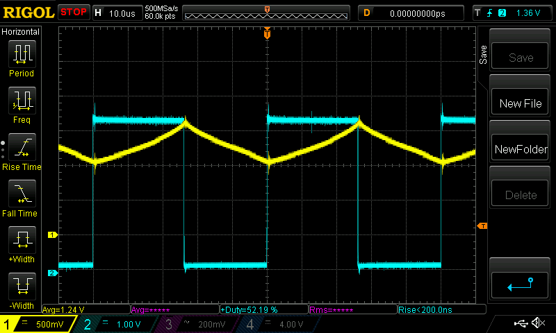 it is showing signs that it might be near saturation. see the sharper rise of current near the peak? and at 1800W, a lot more current is passing through it now. 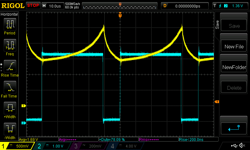 We have saturation here. Clearly we have just about filled the core with all the magnetic energy it can take. Now an inductor of a design and build that I prefer nowadays: at 800W 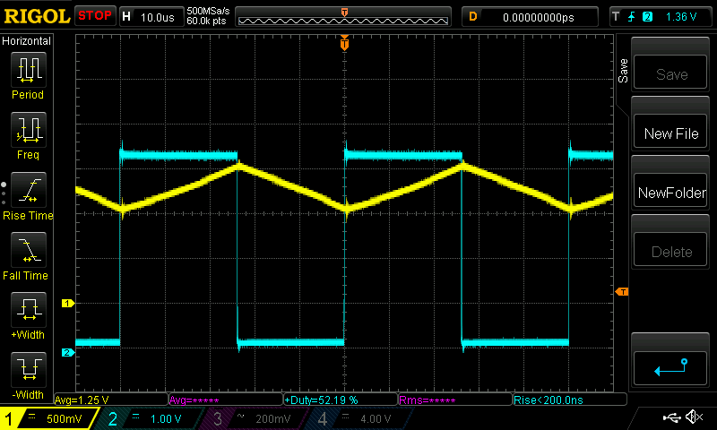 straight line current traces up and down. Perfect. and at 2000W 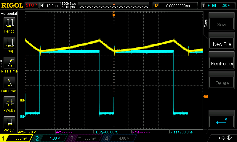 still looking good. This is what I want for the charge controller. Here are the two inductors. Can you tell which is the bad one and which is the good one? 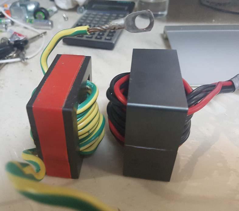 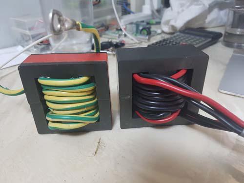 The smaller one with red tape is the bad one right? Small is bad... Well, the smaller one has 9 turns. The bigger one has 5 turns. The smaller one has a 1mm gap in the inner core. The bigger one has no gap. The crap inductor was the bigger one on the right. No air gap means saturation will happen with lower current. The smaller one with red tape is the standard inductor I use for inverter builds. About 47uH. 1mm gap. 9700 Al. 7 to 9 turns. It makes such a difference to the survivability of the inverter I can not begin to express...And they make great candidates for proper sized dc-dc converters. I finally tested the good inductor with 95V input and it saturates too. I probably need a larger inductor with higher current capacity. An easy fix for me is to use two in series. Which I do in the inverters. The Yellow curve clips at the maximum the current sensor can take which is 2.5V output. The saturation is clearly evident with the steeply increasing slope at it nears the peak. This is at 1900W, 95V In, 45V out. 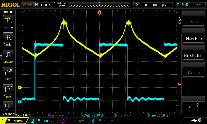 Edited 2020-05-21 21:50 by poida wronger than a phone book full of wrong phone numbers |
||||
| poida Guru Joined: 02/02/2017 Location: AustraliaPosts: 1432 |
I put both inductors in series and the current peak dropped at 2000W to just below the 2.5V clipping point. Clearly 2 in series gives you more current headroom. I just ordered 2 pairs of the 8700 AL 70mm cores. I will give them maybe a 1mm gap each and 7 turns. This will likely be the required inductor design. wronger than a phone book full of wrong phone numbers |
||||
| renewableMark Guru Joined: 09/12/2017 Location: AustraliaPosts: 1678 |
Ahh, now I got you, I didn't read your post carefully enough on the bottom of P13. I got confused when you said you would try the 8700 with a gap. Outstanding work mate.  You might find the inside of chinese mppt's look like yours soon. Cheers Caveman Mark Off grid eastern Melb |
||||
| poida Guru Joined: 02/02/2017 Location: AustraliaPosts: 1432 |
heh, but it does saturate when fed 95V input, 45V output at 2000W. It's looking like we will need MOAR INDUCTANCE!!! 2 in series should do the trick. wronger than a phone book full of wrong phone numbers |
||||
| poida Guru Joined: 02/02/2017 Location: AustraliaPosts: 1432 |
more on saturation - this time efficiency. two tests with 100V or more input, which as we have seen, leads to saturation at 2kW loads and above. 985W output: 108V and 9.4A in, 32.5V and 30.3A out 1016W in, 985W out, that's 97% efficient Testing to 1760W, now we have some saturation, see below 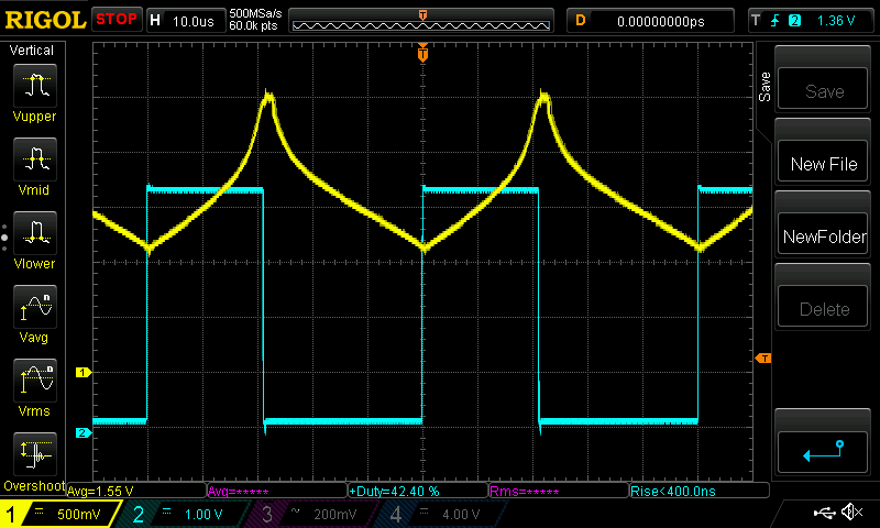 This must give us less efficiency, right? The inductor is no longer exchanging current with magnetic field energy and back again in a nearly lossless manner. 106.8V and 16.8A in, 44.0V and 40.0A out means 1794W in and 1760W out 98 % efficient. My current measurement must have some error, as does the voltage measurement. But I am very surprised to see no hit on efficiency when the ferrite core approaches saturation. The story might be very different at 45A and 57V out, which is 2565W output. Dunno. We will see when the time comes and I do some higher power tests. To get 108V DC I put the Eltek 2kW supply in series with the 52V SLA battery. This is probably not a good idea. And having 108V DC backed up with a lot of capacitance AND about 40 Amps of supply is not a situation where mistakes are only minor things to ignore. If inductor choice becomes hard and expensive, I can always increase pwm frequency. Going from the present 20kHz to 40kHz would double the MOSFET switching losses but also prevent saturation at 2500W @ 100V input while using the same inductors as used in the above tests. I think switching losses will be found to be quite insignificant compared to other losses in the converter. Edited 2020-05-22 10:54 by poida wronger than a phone book full of wrong phone numbers |
||||
| poida Guru Joined: 02/02/2017 Location: AustraliaPosts: 1432 |
the video here is a sneak preview of the LCD display as the prototype is running. 51V in Absorb mode, with 13.7V set point for a 100A 12V SLA. First for a few seconds it is wating until next mppt scan. Then it starts up. And current limits at 30A for a few seconds. The bottom line shows the tracking mode and the battery voltage target which in this case is 13.7V. We can see all the info we need. The last 2 digits at the bottom right are the seconds counter, showing when a mmpt scan will next occur (when it gets to 59) I use this for debugging code, and probably will remove it in production. Current limiting is working well. I set it to limit at 10A and it only outputs 10A Same for any setting. All within about an Amp or 2. The voltage is maintained quite nicely now, with about 0.02V up and down with this 12V battery. here is the DMM showing the output voltage It shows the small variation that the controller produces now. This is much, much better than previous code. Note the DMM shows 13.6x V when the setpoint is 13.7V Calibration of the charge controller is not quite as good as the Fluke. How accurate do we really need it anyway? I am getting close to showing a version of the code. Next task is to adapt this code to run a 40kHz pwm, to permit high voltage inputs with the existing inductors I have here. wronger than a phone book full of wrong phone numbers |
||||
| Warpspeed Guru Joined: 09/08/2007 Location: AustraliaPosts: 4406 |
Great stuff Peter. Rule of thumb with chokes, always pack as many turns as will fit of wire of sufficient gauge to carry the required current. Then adjust the air gap to reach best compromise between saturation level and inductance. If you need more of either, just stack more cores together, and try again. As Peter says, its always very difficult to tell just by looking, whatever you have, needs to be tested. Cheers, ĀTony. |
||||
| poida Guru Joined: 02/02/2017 Location: AustraliaPosts: 1432 |
Earlier today I wondered would the prototype charge controller survive a short on the output terminals. When given a current limited input supply, sure, no problems. The then hooked it up to the 48V SLA bank, with a 20A AC contact breaker and tried again. Nope. No smoke. Just no MOSFETs working as they should. Lucky to have a stock of HY5110 to press into service. So after a bit of time I have something that CAN survive a short on the output. We can use the atmega328p comparator system. (The Nano and Uno use this chip) This means we use pins D6 and d7. I have a set point voltage from a multi turn trimpot on d7 And I have the output of a LEM 16 current sensor going into d6. Now I can short the output with a spanner and no destruction. The firmware once it sees this over current situation just goes into a useless infinite loop, needing a reboot. But the LCD shows "OVERCURRENT" as a clue to the human. Here is how fast it works. Purple is the current limit set point. Yellow is inductor current. Light Blue is PWM. Looking from left to right we see things going well and then the current increases. And then it exceeds the Purple line causing immediate stop of pwm. 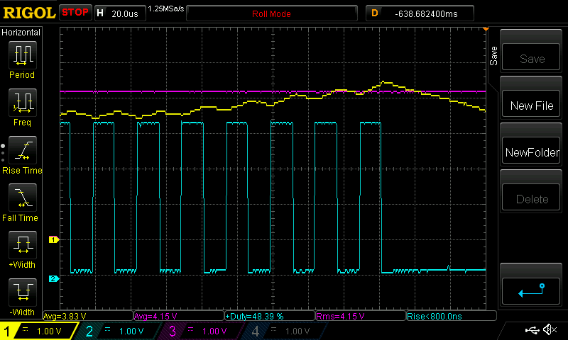 This might be an important addition to the design. Or just leave it off and ensure you do not short the output.. Edited 2020-05-23 17:13 by poida wronger than a phone book full of wrong phone numbers |
||||
| shallowal Regular Member Joined: 26/07/2018 Location: AustraliaPosts: 58 |
Wow!!, great work there Poida. Having just lost another bunch of components on my Mad-inverter, I'm all for a fast acting, Mosfet saving protection system.  Allan Allan |
||||
| nickskethisniks Guru Joined: 17/10/2017 Location: BelgiumPosts: 462 |
Impressive! That's shows how little I know of the 328 datasheet... So in theory you could do cycle by cycle current limit? Not that it's needed over here, short circuit/overcurrent says something is wrong. So the comparator gives some kind of interupt? I'm getting more and more curious about your code. OH would it ben possible to upload the final pcb files? Then I ad them to my projectfiles on easyeda. Edited 2020-05-23 17:31 by nickskethisniks |
||||
| poida Guru Joined: 02/02/2017 Location: AustraliaPosts: 1432 |
this project is not really useful in your situation. I suspect you would need to build something custom to get this kind of thing going on. wronger than a phone book full of wrong phone numbers |
||||
| poida Guru Joined: 02/02/2017 Location: AustraliaPosts: 1432 |
I tried using the interrupt function but it was a pain in the arse. It kept calling the interrupt many times and things just went from bad to worse. The code now looks at the comparator result (either = 0 where d7>d6 or = 1 iwhen d7<d6....or the other way around..) each time the 40kHz pwm interrupt occurs. If it finds =1 then it stops the pwm duty cycle and stuffs up the normal running of my program so that it needs a reboot. This is OK with me. I foresee the controller will be built with this over current addition and setup so that it will trigger when inductor currents are way,way above normal values. It will need a good current sensor, and some skill in setting up. I think only a DMM is all that is needed. Also, I think we can use not only the LEM LTS 16 series sensors but also the Alllegro sensors. I thought that in the event of a short circuit, the inductor current will increase pwm cycle by cycle until it exceeds a defined value. Then I can stop pwm immediately. That is what I am doing and I think all it has to do is protect the controller from destruction and then it has achieved it's goal. I think cycle by cycle current control might be possible but not worth it. All I want is a controller that will survive. Maybe not be 100% the best, just 95% good enough. Mike did the dc-dc converter design work in Altium and so there is no way to import those files into easyeda. (even though easyeda can export files that work well for Altium.) wronger than a phone book full of wrong phone numbers |
||||
| wiseguy Guru Joined: 21/06/2018 Location: AustraliaPosts: 1206 |
Nicks, if you pm me, I can email you the gerbers and original files. Altium can export to some other formats, I will give you the list, Āperhaps one of these might be EDA friendly ? Peter, great outcome with the overcurrent shutdown, it looks to work a treat. Ā Wondering if a restart after a predetermined time out might be ok too? ĀIf it is as well behaved as it looks, you don't have to be there to press the button to make it work again. ĀIe 5 minutes has passed lets try again to see if I'm still over-current. I'm not saying I want or need this feature but someone/others might see this as a benefit ? Ive been thinking about the current sensors and calibration and provide the following if it may be considered useful. In some previous similar designs I have incorporated a single switch on the micro board. Holding in the switch for 5 seconds enters a calibration routine, first The FETS are off and the outputs of current sensors one and two are stored as zero (~ 2.5V), then press the button which stores the zero value & turns the FETs hard on. Now pass a known current say 20A through both sensors then press the button again to store this value, note this may be 5A with 4 loops through the sensor (the heavy gauge wire is fitted after calibration or they wont all fit. Ā(there can be a third step that calibrates an output max (excessive) output current level, causing timeout & restart. Then set the voltage in, to 50V and the next (last) press of the button calibrates the input & output voltages. ĀThis method does not require anything other than a basic multimeter and variable power supply to complete. ĀOtherwise it is done with a serial link, laptop and the same multimeter & power supply & more software. In the field, to recalibrate you can enter the calibration routine again by inputting 25V +/- 1V and pressing the button again for 5 seconds - apart from this specific condition, the button is ignored forever after the initial calibration. Longer term drift in the current sensors is compensated by re-storing the zero current offset voltage, each day before driving the FETs & passing any current, each time it is ready to do its MPPT after having power applied at the input. I do not want feedback about this being a poor or bad idea - it DOES work and is in use in thousands of products on a daily basis, that were set up & used in this manner. ĀIts Ok if you hate it, it works for me. ĀThere are further calibration steps in my product to also set min and max input voltage shutdown. A single LED flashing or steady is a big help during the cal process steps, for visual feedback. Edited 2020-05-24 15:49 by wiseguy If at first you dont succeed, I suggest you avoid sky diving.... Cheers Mike |
||||
| The Back Shed's forum code is written, and hosted, in Australia. | © JAQ Software 2025 |
