
|
|
Forum Index : Electronics : 150V 45A MPPT - roll your own
| Author | Message | ||||
| poida Guru Joined: 02/02/2017 Location: AustraliaPosts: 1389 |
good progress with code. I have settled on an unpleasant choice in the project. I suspect I2C interface can on occasion cause some mistiming with the pwm, particularly when in NIGHT mode. I don't like it. When using the arduino softwareserial library, I find no problems at all. This has resulted in a couple of things. The I2C 4 pin connector is not needed for I2C. But we can re-purpose one of the pins to be TX for softwareserial. I choose A5 which was used for the I2C and so we can still use the 4 pin connector. This means you need another nano, to do the translation from serial to IC2. I had a quick look and saw no 20x4 LCD with serial input on aliexpress. They all seem to have I2C. Maybe we can find them somewhere. I have tested: - mppt -> absorb transtion - absorb timer, which leads to.. - transition to float - EQ, to run for a define time - EQ cancel due to low bv, then back to mppt/absorb - float cancel due to low bv, leading back to mppt/absorb - timeout for bv drop while in EQ - timeout for bv drop while in absorb - timeout for bv drop while in float The "hardware" overcurrent still works fine, and once triggered pwm goes to near zero and after 60 seconds, it permits normal operation. Which is a max power scan and into mppt track mode. Lots of things are set up via the usb serial console. Here is what it looks like now: A - max heat sink temp 100 degC B - max inductor temp 100 degC C - cal. Input Volts 0.0885 ( 28.14 V) D - cal. Output Volts 0.0893 ( 12.68 V) E - cal. Input Amps 0.1173 ( 0.12 A) F - cal. Output Amps 0.1173 ( -0.00 A) G - zero Iin sensor 518 ADC counts H - zero Iout sensor 518 ADC counts I - Max battery Volts 15.00 Volts J - Absorb voltage 13.50 Volts K - Absorb tolerence 0.50 Volts L - Maximum Current 30.00 Amps M - Night power 10.00 Watts N - Zero Energy total 0.00 kW.hr O - Equalisation voltage 15.00 Volts P - EQ duration 60.00 minutes Q - EQ reset voltage 14.50 Volts R - Absorb duration 60.00 minutes S - Float voltage 12.70 Volts T - Float tolerence 0.50 Volts U - fast OC enable 1 (ON = 1, OFF = 0) Z - Write defaults We can choose to enable the hardware overcurrent protection now. If you choose to not build in the current sensor needed for this, disabling it might be the way to go. The brainboard will need a bit of extra soldering, for the overcurrent protection. Two wires for the set point and current signal, one for 5V, one for ground. And a trimpot to set the setpoint. Not too bad. Maybe add this to v2 of the board. wronger than a phone book full of wrong phone numbers |
||||
| Solar Mike Guru Joined: 08/02/2015 Location: New ZealandPosts: 1124 |
You can get Serial display adapters here Cheers Mike |
||||
| SYM-1 Newbie Joined: 18/10/2019 Location: New ZealandPosts: 40 |
20x4 LCD�s with 4 bit parallel are easy to obtain but you need 6 I/O pins. They are quite easy to use. I have a tutorial somewhere but are there 6 pins available? Persistence is the key |
||||
renewableMark Guru Joined: 09/12/2017 Location: AustraliaPosts: 1678 |
It's going to be cheaper (and more easily accessible) to just use a second nano. On Ali they are $38 for 10 Cheers Caveman Mark Off grid eastern Melb |
||||
| poida Guru Joined: 02/02/2017 Location: AustraliaPosts: 1389 |
yup. That is the way to go. wronger than a phone book full of wrong phone numbers |
||||
| poida Guru Joined: 02/02/2017 Location: AustraliaPosts: 1389 |
The Inductor: Earlier I compared one inductor to another. The big one which saturated with too low current, (the one on the right) 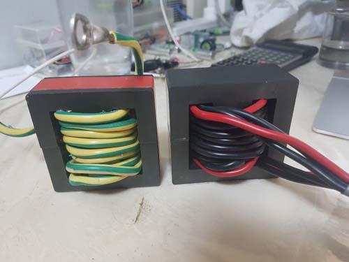 had I think 5 turns and no gap. I rebuilt it today with a gap. Now it's 37uH with 8 turns. Here is the gap I chiselled with blunt instruments. In my view the magnetic field in the air gap does not care very much how good the workmanship is with the cutting of the gap. There are still remnants of the epoxy on various edges too. I made a gap of 1.5mm 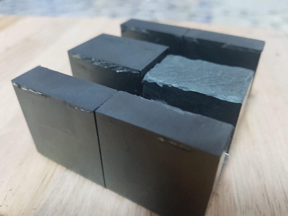 How does it perform, with 108V input, 2kW out and 20kHz pwm? Recall this test shows clear signs of saturation with all the combinations of inductors I have tested so far. Really well as it happens. This is all I need for the controller. 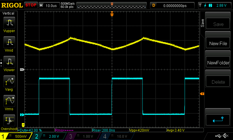 (from the DSO) zero current = 2.53V peak to peak current is 0.42V average current is 3.4V with a current sensor giving 0.0202 V/Amp we can see the average current through the inductor (and through the load too) is (3.4 - 2.53)/0.0202 = 43 Amps. This is confirmed by the current sensor on the output of the converter board. The ripple current is 0.42 / 0.202 = 20 Amps. This is sort of 50% ripple. It might lead to heating up of the output capacitors. But no saturation. I thought I would eventually arrive at a suitable inductor. I like how this one can cope with 20kHz pwm. Even though I test to 2kW and the design output power is 45A at 57V which is 2565W I think this will be good enough. I doubt many of us will have a battery sucking 45A at this absorb voltage for hours on end, assuming a 48V lead acid bank. And here it is at 2450W 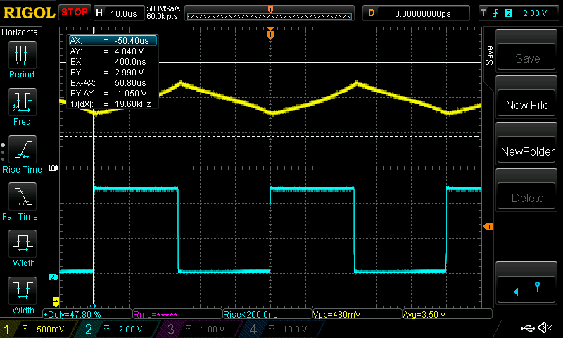 this is good. I will do the same thing with the RS components ferrite core pairs that are available and are quite affordable (RS Stock No.647-9367) when they ever arrive. First test with zero gap, then with 1mm, then with probable end choice of 1.5mm After 5 minutes at 2kW, the output caps are still cold. So 20Amp ripple is no problem. Edited 2020-05-31 18:13 by poida wronger than a phone book full of wrong phone numbers |
||||
| poida Guru Joined: 02/02/2017 Location: AustraliaPosts: 1389 |
After discovering the need for over current protection, I thought it best to review the brainboard. I have 25 boards coming from JCLPCB soon but I think I will order another 25 of these, to replace them: 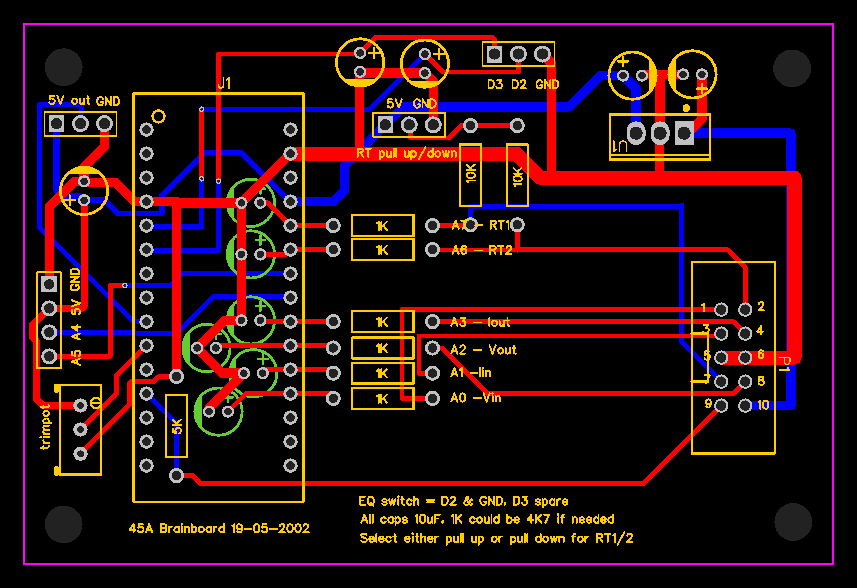 which have provision for a multi turn trimpot to set the max current and a 3 pin header for the current sensor. This later board design will avoid needing a small hack that has a trimpot, some leads hand soldered to the nano and what-not. The current sensor will need be be something capable of 100 Amps or more. Allegro make some that do that. I am using a LEM LTS 16 with a shunt. (this is the sensor that I used in prior DSO captures, with it's 0.0202V/Amp sensitivity.) I think that all we need is to have a current sensor on one of the inductor leads, with 3 wires coming back to the brainboard, to the 3 pin header. So if I get these boards, it will be another 2 - 3 weeks before I send out power and brain boards to those who want them. I want to combine postage and send out both a brainboard and power board as a unit. Edited 2020-06-01 20:31 by poida wronger than a phone book full of wrong phone numbers |
||||
| wiseguy Guru Joined: 21/06/2018 Location: AustraliaPosts: 998 |
Looking better every day Peter ! Some thinking out loud about where to get bits from, what type and and how much to pay. If you are scrounging parts from used inverters you can save a lot of the cost. The more expensive parts are the 13 x Electrolytic caps, 2 x current sensors and the Mosfets If you have to buy new parts then you can be a little selective & creative. The 470u RS component Cap Poida suggested as a candidate is specified at ripple current 1.45A and 13 cost ~$75 From the spec sheet 9 input caps yield 4,230uF & are rated for a ripple current ~13A. 4 output caps is ~ 1,880uF and ripple current ~ 5.8A If you cannot salvage parts and have to buy new there are other selections that can be cost effective. I would propose that you could start an account with digikey (www.digikey.com.au) which is a straightforward process. They ship for free for orders >$60 Au, the caps I suggest to purchase instead of the RS ones are digikey 493-8524-ND. These caps are 200V @ 1200uF and have a 6A ripple rating, 7 will cost ~ $63. So 5 for the input will be 6000uF @ 30A ripple. 2 for the output will be 2,400uF @ 12A ripple If a bulk order was organised 100Caps cost is ~ $6.65ea so using an extra input and output capacitor is still around $60 giving input ripple at 36A and output ripple of 18A. This entails someone to organise and post out etc - sorry but I cant do it myself, I am currently overcommitted. The ripple rating of the output caps is not as important when you have a battery attached, which is really a big lead acid capacitor. So while at the website check out their pricing for anything else you need - the postage for any extras is free now (for extra items ordered at the same time). Delivery is pretty fast, the week before last I ordered on a Thursday afternoon and had the parts by the following Tuesday. Otherwise the parts list looked right to me Peter. Edited 2020-06-01 22:21 by wiseguy If at first you dont succeed, I suggest you avoid sky diving.... Cheers Mike |
||||
| nickskethisniks Guru Joined: 17/10/2017 Location: BelgiumPosts: 415 |
Poida what I sometimes do is fill the empty space on the pcb with via's (exposed copper) so I could add some stuff later on. Like an experimentation pcb. |
||||
| wiseguy Guru Joined: 21/06/2018 Location: AustraliaPosts: 998 |
Good point Nicks, I often do that too, & Peter dont forget that small via holes can add extra cost - the ones on the PCB shown look like a pretty small drill, they should be around 0.5mm (or whatever minimum hole the pcb manufacturer can do before adding cost). & remember to keep the PCB dimensions within 100 x 100mm If at first you dont succeed, I suggest you avoid sky diving.... Cheers Mike |
||||
| shallowal Regular Member Joined: 26/07/2018 Location: AustraliaPosts: 58 |
BTW the date is wrong on the Brainboard Peter. Should be 2020 NOT 2002.  Allan Allan |
||||
| SYM-1 Newbie Joined: 18/10/2019 Location: New ZealandPosts: 40 |
Sorry if this is a silly question. Poida - you said' "I am using a LEM LTS 16 with a shunt." I have never used a hall effect sensor but I don't understand why you need both a shunt and a hall effect sensor. A shunt converts current to voltage and I understand a hall effect sensor measures the current and gives a voltage output - so don't they both do the same thing? Perhaps you meant shunt amplifier. I am only guessing though. On another matter - I hope its not too off topic - I while ago I cobbled together a dc to dc converter using a micromite and an iron core inductor I had lying around. The inductor would not transmit much energy if I ran it above 100Hz or so but apart from that I could get 30A through it. Is there any disadvantage to using low frequencies like this (apart from the cost of the inductors if you don't have them lying around). Grant Persistence is the key |
||||
| poida Guru Joined: 02/02/2017 Location: AustraliaPosts: 1389 |
Grant: the current sensor I use to obtain the current through the inductor is only +/- 50Amps. Any more and the output signal saturates at about +5.0V or 0V depending on the direction of flow. So I put a 4mm diameter copper wire in parallel to the sensor, taking about 1/2 the current, and letting the other half pass through the sensor. Now I have a sensor that can give good indications of current up to about 100 Amps. The sensitivity of course goes down from 0.042V/Amp to 0.0202V/Amp but what I need is it to work at levels near 100 Amps. Iron core inductors are great for low frequencies. 50Hz current limiting of 240V bay lights, fluoro tubes etc. providing the flyback voltage spike to ignite the tube. This project has nominal specifications of 100V input 50V out 45 Amps out I chose 20kHz pwm so as to permit the use of inductors of the type and current rating that we have used in the past when we built inverters here. A typical size ferrite core such as the 70x33x32 RS part no. 647-9367 I hope be able to store the energy required with the 50% duty cycle at 20kHz and 100V. 20kHz means 50us period of the pwm. 50% duty cycle means the inductor is conducting the 100V for 25us If we go to 100Hz switching, then the inductor will need to conduct 100V for 5ms When testing inductors on the bench with the pulse tester, I can determine the inductance from recording the change in current, the pulse time and the supply voltage and using L = V x s / A s = time, A is Amps, V is volts All things being equal, the inductance needed for a change to 100 Hz from 20kHz would be 200 times bigger. We would need a massive inductor. I have ended up with an inductor choice of the above core or something similar, with a 1.5mm air gap, 8 turns. With the 50% duty cycle, 100V and 20kHz I find it can handle 3000W without taking peak current levels beyond about 70A. 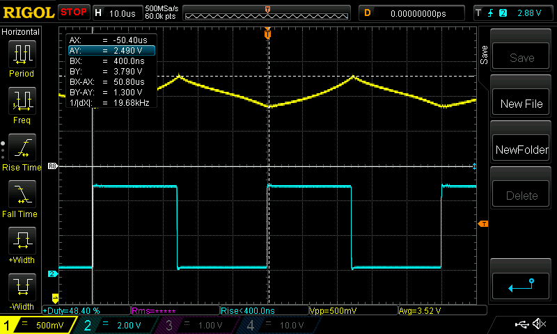 Yellow is the current sensor, with 0.5V/div and 0.0202V/Amp Blue is pwm. We can see the current increase when the DC supply is switched through the inductor. Then the switch opens and current now drops. The cursor line is at 1.3V from the 2.5V zero output of the sensor. This is 64 Amps at the peak. The low point of the current waveform is at 3.35V, that is 40A. So the current grows 24A over the 24uSec period. With much longer switch ON periods, the inductor will have to store massive amounts of energy. 100Hz is not feasible. wronger than a phone book full of wrong phone numbers |
||||
| Warpspeed Guru Joined: 09/08/2007 Location: AustraliaPosts: 4406 |
Grant, There are three fundamentally different types of Hall sensor you can buy. The first type is just the actual Hall element itself, that only puts out a very weak millivolt signal, that needs to be used with an external amplifier. Those are the real cheapies. The next step up are the Hall sensors that have an internal dc amplifier that provides typically an 0.5v to 4.5v signal when powered from +5v. The best and most accurate Hall sensors, also have an internal amplifier, but work in a very different way. The current you are measuring passes through a magnetic core, and induces a magnetic flux in the core which the Hall device senses. Wound around the core is a coil, often with 1,000 turns. Output from the Hall sensor goes to a very high gain feedback amplifier which controls the current through this coil. Its a very high gain feedback system, and the amplifier constantly nulls the flux in the magnetic core back to zero. If you are measuring a 6.1 amp current, the current through the 1,000 turn coil balances out at EXACTLY 6.1mA in order to zero the system. �This gives extremely stable and linear measurement with a very accurate zero. The output from the device will be a current (not a voltage) and if it has the usual 1,000 turn coil, it will output 1mA for every amp being measured. The LA55P sensor is like this. So to turn the current coming out of the device into a usable voltage, a current shunt is required. A 1K shunt would produce 1v per mA or 1v for each original amp being measured. The LA55P recommends a 100 ohm shunt which would produce 50mA through the shunt at 50 amps, producing 5.0 volts output. Or you could use a 10 ohm shunt and get 0.5v for 50 measured amps. https://pdf1.alldatasheet.com/datasheet-pdf/view/115009/LEM/LA55P.html Edited 2020-06-02 10:20 by Warpspeed Cheers, �Tony. |
||||
| poida Guru Joined: 02/02/2017 Location: AustraliaPosts: 1389 |
The boards have arrived today. I ordered them 15th May. This is 12 days or so turnaround. Last night I ordered 25 of the version 2 brainboards with the added trimpot and 3 pin header for the over current sense. There are choices to be made I suppose. I post you the boards, including version 1 brainboards now. And post again v.2 brainboards later. You end up paying 2x postage. or I wait and post both brainboard versions with the power boards. so that's 1x postage. 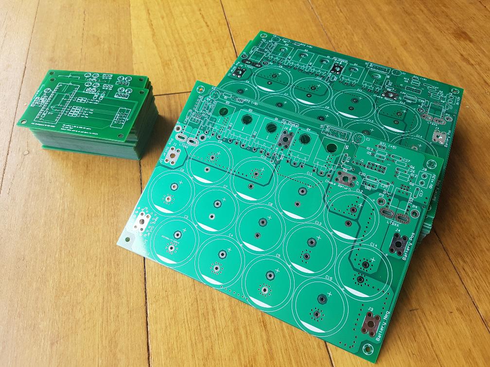 Shallowal: the date typo is going to be a feature I'm afraid. Too late to change. Nicks: That's probably a good idea but I tend to do the experimenting using flying wires. The over current sense works perfectly well with 6 inch wires everywhere picking up EMI etc. Wiseguy: The tiny vias are built in from EasyEDA PCB editor, I use defaults. Since JCLPCB is closely aligned with EAsyEDA I figure their users would be given cost effective and sensible defaults. When ordering the boards I found no option to reduce cost by via diameter choices. I reckon the vias are done with a laser and the sizes they get the easiest are the sizes baked into EasyEDA defaults. Who knows. I too was looking at cap choices. The one in the parts list is just a start point and there are better options with lower cost & better performance. I think I will use 1,000uF 200V caps with 4A ripple, maybe mix 4 x 1000 + 1 x 470 for the DC supply, and 2 x 1000 + 1 x 470 on the output. Don't know yet. But it would be best to keep the total capacitance to about 4,250uF and 2,350uF so that the firmware has a chance to work well. +/- 30% or so.. Probably well worth the time to have a look at digikey's caps, those ones you found look ideal and cost effective. I find RS to be a lot slower with COVID19, I think I will start an account at digikey. There will be a few changes to the build as we go. For a start, the 2K7 on the input voltage divider (with the 47K) is too high for voltages over about 90V. Depending on your application, you might be OK with this. Else a different resistor will be needed. I calculate 2K should be good for 120V input, to give the Nano a less than 5V input to the ADC channel, about 4.9V actually. I attach a good sized rendering of the power board schematic for reference. Screen Shot 2020-05-30 at 10.28.02 am.png.zip Last night I had a prototype pumping 3kW into the 1 Ohm Blue Bucket of Resistance. No problems. Since I have built 3 boards using Nick's PCB, maybe it's time to rip the parts off one and build one using Wiseguy's... wronger than a phone book full of wrong phone numbers |
||||
| poida Guru Joined: 02/02/2017 Location: AustraliaPosts: 1389 |
Also, I bought a pack of 100 slipad things for TO-247. I plan to chuck in 4 of these per board in the packages I send out, until I run out of pads. wronger than a phone book full of wrong phone numbers |
||||
| shallowal Regular Member Joined: 26/07/2018 Location: AustraliaPosts: 58 |
I've made a couple of orders with Digikey in the last few weeks and am amazed at how quickly they turn up. Less than a week to a country location. As far as boards go, I'm happy to wait for the updated boards. Allan |
||||
| SYM-1 Newbie Joined: 18/10/2019 Location: New ZealandPosts: 40 |
Thanks for the info on the current sensing and the decision making on the frequency. I am happy to wait for everything to be sent together. Grant Persistence is the key |
||||
| poida Guru Joined: 02/02/2017 Location: AustraliaPosts: 1389 |
I built a brainboard and it runs Nick's power board really well. It's much nicer to not have wires and crap everywhere now. The sensed inputs (Vin,Iin, Vout,Iout etc) are clean and the closed loop control runs smoothly. Important this, it depends on a clean input. (I can get a DSO probe on pwm output too!) 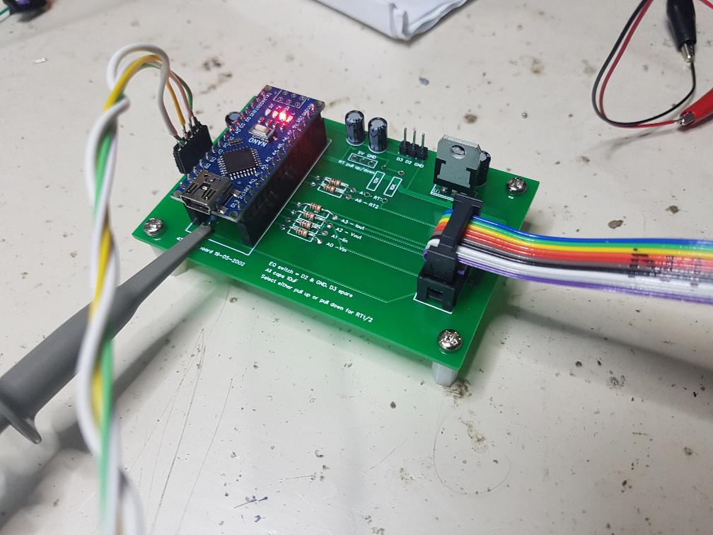 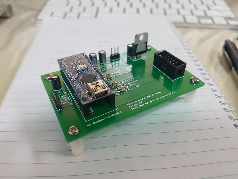 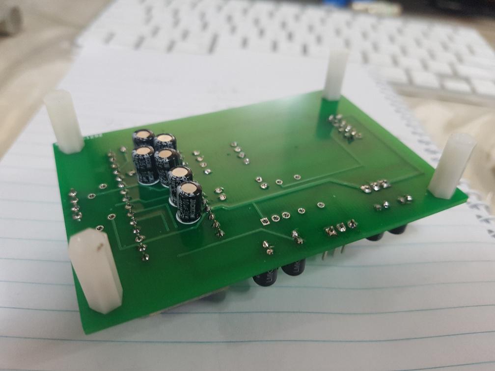 I did not fit the 2K2 resistors for I2C since they are not needed any more. Also, no pullup/down for the NTC since I have not connected them to the power board yet. I used 1K resistors for the low pass filter for the 4 inputs to see how they go. The signals are not too bad at all. If needed we can use 4K7 or larger to kill more noise. Pout/10 Pin/10 Vin Vout Iin Iout 200 Setpoint 85.91 86.57 49.12 28.17 17.62 30.50 200 28.20 86.74 86.93 49.12 28.23 17.70 30.72 200 28.20 86.41 86.54 49.12 28.24 17.62 30.60 200 28.20 86.73 87.05 49.12 28.26 17.72 30.69 200 28.21 85.86 86.52 49.12 28.15 17.61 30.50 200 28.20 86.92 87.22 49.12 28.26 17.76 30.76 200 28.21 85.89 86.54 49.12 28.17 17.62 30.49 200 28.20 86.56 86.79 49.14 28.17 17.66 30.73 200 28.20 86.79 86.93 49.12 28.22 17.70 30.75 200 28.20 86.31 86.55 49.12 28.17 17.62 30.64 200 28.21 85.87 86.54 49.12 28.17 17.62 30.48 200 28.20 86.52 86.53 49.12 28.26 17.61 30.61 200 28.20 86.14 86.55 49.12 28.18 17.62 30.57 200 28.20 86.56 86.77 49.12 28.26 17.67 30.63 200 28.21 85.87 86.50 49.12 28.17 17.61 30.48 200 28.21 86.86 87.22 49.12 28.24 17.76 30.76 200 28.20 86.34 86.65 49.12 28.16 17.64 30.66 200 28.20 86.82 87.09 49.12 28.23 17.73 30.75 200 28.21 The 17.6 column is Iin, not a lot of noise. 30.7 is Iout and there is a bit more. This of course could well be due to relatively bad PCB trace routing for this signal. Vin is 49.12, steady as. 28.23 column is Vout, again a bit noisy due to the long run past the switching node. Mike's PCB addresses this issue and has a good many detail improvements and I expect clean signals for all 4 inputs. I could run the house on this thing already. wronger than a phone book full of wrong phone numbers |
||||
Revlac Guru Joined: 31/12/2016 Location: AustraliaPosts: 961 |
Also more than happy to wait, AUS Post has made plenty of profit anyway. Boards are looking nice. Cheers Aaron Off The Grid |
||||
