
|
|
Forum Index : Electronics : 150V 45A MPPT - roll your own
| Author | Message | ||||
renewableMark Guru Joined: 09/12/2017 Location: AustraliaPosts: 1678 |
Tony, no need for armour, my unit running flawlessly for probably close to 2 years now is testament to all your calculations. Tuning my unit for 75 Hz and building that nice choke stopped all my issues. That's why I'm keen to investigate the iron chokes. My wife has really given that poor machine absolute hell, she basically said the system has to do what the power lines can do or it's not worth it. But bugger me, it's stood up to it. Mad power board, nano control board, Warp calculations for torroid, choke and tuning to 75 have been a winning combination. Cheers Caveman Mark Off grid eastern Melb |
||||
| wiseguy Guru Joined: 21/06/2018 Location: AustraliaPosts: 1001 |
Thanks Tony, I was shooting from the hip - If the core heat was being increased due to entering saturation I thought that reducing the flux a bit might also reduce the heating a lot. I suspected that if saturation was the cause of the heat it is probably a non linear relationship between the flux near sat & the generated heat. If at first you dont succeed, I suggest you avoid sky diving.... Cheers Mike |
||||
| Warpspeed Guru Joined: 09/08/2007 Location: AustraliaPosts: 4406 |
Its been a team effort, and together we can achieve some very great things. I am a complete software dumb ass. But if we all work together nothing can stop us. Cheers, ĀTony. |
||||
| johnmc Senior Member Joined: 21/01/2011 Location: AustraliaPosts: 282 |
I thank the whole team at the back shed for their sharing of knowledge, and their willingness to help . Especially us complete electronic dumb arses. Cheers and best wishes john johnmc |
||||
| poida Guru Joined: 02/02/2017 Location: AustraliaPosts: 1391 |
I have tested the converter, using 2 inductors in series. 2 of the E 70/33/32 N27 type material, with 1.5 to 1.6mm gaps Both have 7 turns. The prior test I did here where I vary the pwm frequency from 20 to 40 then 80 kHz I used one inductor in that test. the results were: 20kHz: in 106.4V, 20.2A, 2150W out 47.8V, 42.7A, 2041W, 94.9% conversion efficiency 37A ripple current 40kHz: in 106.6V, 20.7A, 2200W out 47.8V, 42.6A, 2036W, 92.5% 21A ripple current 80kHz: in 109.4V,20.7A, 2264W out 47.1V, 44.0A, 2072W, 91.5% 11.5A ripple We found that one inductor at 20kHz gave current ripple levels of about 37 Amps which is about 2x more than acceptable. A simple fix to reduce this ripple is to use faster pwm frequencies. I found it cost about 50W to go from 20kHz to 40kHz but it reduced ripple to about 21 Amps. The latest results, using 2 inductors in series is: in 106.7V, 20.7A, 2208W out 47.0V, 44.1A, 2073W, 93.9% conversion efficiency 25A ripple The cost for 2 inductors is AUD $52 for the 2 pairs of cores. The 7 turns in each, with the PVC insulated wire add up to quite small DC resistance losses (I have found them to be about 0.004 Ohms each). Also I find these inductors easy to make. I think it is both interesting and potentially valuable that Wiseguy and Warp are keen to look at the Sendust toroid cores for this application. I hope they discover an even more efficient solution and I expect they will. I won't participate in the work characterising sendust toroids since I am happy with the $52 E core solution I have at hand. I expect there to be no need to alter anything in the code to accommodate builds that use sendust cores either. It would be trivial to provide an option to use 20kHz pwm or 40kHz pwm and I think I will add this feature anyway. This will allow us to experiment with different gate drive regimes and to exploit a better performing design to a fuller extent. I have many questions to reply to and I plan to answer them in a little while. I could not send out the boards today. I had to go bird watching with my wife. If had said no to the bird outing life would have taken a nasty but avoidable turn. I can get to the post office on Monday. wronger than a phone book full of wrong phone numbers |
||||
| SYM-1 Newbie Joined: 18/10/2019 Location: New ZealandPosts: 40 |
I have ordered a 7ö torroid and I have a 30A iron core - long core stelloy that I would like to give a try too. I would have to lower the frequency for the stelloy core but I expect that it wonÆt be too difficult to do. I also have some 4ö cores which I could double up. I have a bunch of lifepo4 batteries I could use as a real load rather than dumping the load into avresistor. i donÆt know ehat their high frequency response is likely to be but am keen to experiment with s range of frequencies. I have a bunch of solar panels too but not on the roof at this stage but I can do simulations from a 150V 30A supply. Persistence is the key |
||||
| poida Guru Joined: 02/02/2017 Location: AustraliaPosts: 1391 |
Warp, I think I have found a design that does work. It works up to my design limits and it works down to very low output levels. It works in continuous conduction mode and it also works in discontinuous conduction mode. During the testing of prototypes of this project, I have never experienced a loss of control of the closed loop system. It has always converged to a stable output. I can not count how many times I have fired it up and ran it up to power, down to zero load, diconnected load, connected a load, disconnected the input, connected the input, etc. It must count in the hundreds now. No out of control loop behaviour. (I have some practical background in closed loop control systems: The theoretical study of closed loop systems requires maths that is beyond me. Laplace transforms, S parameters, Bode plots, Zeros and Poles... I choose to get my hands dirty in safe ways that do no damage things and that obtain working systems via trail and error. I have seen out of control closed loop systems in both my hobbies at home and as well as in my paid work. I developed from scratch a new control system for our 3 axis AC servo driven 3 meter x 3 meter industrial sewing machine quilting system. We paid $250,000 for it. There was significant risks that out of control servo systems would do some real & costly damage. I made the new control system from scratch, working with servo drives and their control systems. It has been functional for 4 months now with zero issues.) I have seen out of control closed loop systems in my inverter software development. The mppt controller is very well behaved and nothing upsets it. I made some video of a test I prepared for you. 110V input, 13V output, connected to a 100AH SLA battery. 1 x 47uH E core ferrite with 1.5mm gap 20kHz pwm The battery is fully charged. Output current is less than 0.5A. This is about 6W. https://youtu.be/RY2hbPSLVH4 The DSO shows 4 lines. Light Blue is PWM, Dark Blue is inductor/switch node voltage, Yellow is inductor current. Purple is max current limit. The video starts with a steady state, the mppt code is in FLOAT mode, maintaining 13V on the output. A small pwm width is required for this. Small changes in pwm width result in large output voltage changes, and so the pwm width is cycling up and down a bit. The DVM shows output voltage is steady to less than +/-0.02V which is good enough for me. I then apply a 6 Amp load to the battery, being a car headlamp. Immediately pwm width increases to maintain the 13V output. Then I remove the load. The battery voltage increases to more than 13V and so PWM is not needed, the code waits. And waits. And waits until output voltage drops below FLOAT's 13V and then restarts pwm, with some small width. This now maintains the required FLOAT voltage of 13V. The code and charge controller system handles all this perfectly and without any instability. The controller is operating in discontinuous mode for nearly all of the time too. There is obviously a large amount of pwm width variance when maintaining the 13V into a charged battery in the video. This is not an unstable closed loop in operation. This is a stable closed loop in operation. If you require near zero variance in pwm duty width it might be possible but I think such a requirement provides little or no benefits. I would not be able to make the firmware achieve this anyway. I am happy to provide videos of any test conditions you and anyone else here would like to see, to build confidence in the project's behavior. wronger than a phone book full of wrong phone numbers |
||||
| renewableMark Guru Joined: 09/12/2017 Location: AustraliaPosts: 1678 |
So this is the one used yeah? If two sets of those work ok then that's good. Do you want to test any of the steel cores people may already have in draws? Edit, yes, I'm a pain in the ass. Edited 2020-06-13 15:59 by renewableMark Cheers Caveman Mark Off grid eastern Melb |
||||
| poida Guru Joined: 02/02/2017 Location: AustraliaPosts: 1391 |
yup, those cores are the ones I have used. 1.5 - 1.6mm gap on the inner leg. I put a 1.5mm gap on one and left the other half untouched. wronger than a phone book full of wrong phone numbers |
||||
| wiseguy Guru Joined: 21/06/2018 Location: AustraliaPosts: 1001 |
Tony maybe you should not be so quick to put down ideas. I plugged in the values and added a second core as I suggested, unless I am doing something wrong (which I dont think because I got the same figures as Mike before stacking the second core). By also adding 5 more turns, the temperature dropped from 33.97 down to 16.5 degrees and the total core loss went from 33.97 down to 11.02 total circuit loss went down from 37.89 to 17.18 so the losses did not remain constant it became a bit more than 50% more efficient. Ripple current went from 20.7A to 9.56A. This is for the 20kHz frequency. At 40 kHz temp reduced further from Mikes figures of 26.6 down to 12 degrees. Total losses from 22.44 went down to 11.75 and ripple reduced from 11A down to 5A. So overall I believe stacking two or more cores can reduce losses and increase efficiency and reduce ripple - I have not perfected a design just spent a few minutes playing using the core Mike suggested. Mike used 150V as VL during on time and 50V VL during off time. I believe that VL should be Vin minus Vout (150 - 50) which is only 100V, which would make his and my calculations even better again. Mounts trusty steed, sharpens lance and gallops into the distance AFAP. If at first you dont succeed, I suggest you avoid sky diving.... Cheers Mike |
||||
| Warpspeed Guru Joined: 09/08/2007 Location: AustraliaPosts: 4406 |
Yes you are quite right Mike, and I now see where I made my very embarrassing error. If you take a peek at the loss curves at the top right hand corner of the T400 data sheet, you will see all the pretty coloured lines appear to be straight. BUT the vertical scale for core loss is logarithmic. The flux density with two cores will be halved, but the reduction in core loss will be much greater. Likewise small increases if ac flux swing can lead to a spectacular increase in core loss and temperature rise. T400-26D-DataSheet.pdf I should have realised this from testing large steel inverter toroids for magnetising current. Reducing flux swing by adding extra turns, has a very dramatic effect on idling current. Its definitely not a direct linear relationship, in fact its quite dramatic. Warpspeed slaps himself in the head. Edited 2020-06-13 19:19 by Warpspeed Cheers, ĀTony. |
||||
| poida Guru Joined: 02/02/2017 Location: AustraliaPosts: 1391 |
Skin effect is significant at these frequencies and waveforms. The pwm switching forces a square wave shaped voltage flow through the inductor. There is not just 20kHz at (Vin - Vout), there is 60kHz at 1/3 amplitude, and 100kHz at 1/5th , etc.. For sure I am heating the wire in the inductor to a needless degree. I do not have any Litz wire of the length and size needed. It would be a very good test to compare Litz to PCV copper of the same area. I wonder if the higher pwm frequencies with Litz retain the same effeciency as that at 20kHz... I need 1.5m of 4.5mm2 Litz wire to do the test. I look at overall conversion efficiency and try experements varying only one thing, to learn of it's effects on efficiency. The recent tests of 20,40 and 80kHz pwm, and the test with 2 inductors @ 20kHz showed to me a suitable choice would be the 20kHz & 2 inductors for lowest losses while avoiding saturation at 2500W / 110 V input. wronger than a phone book full of wrong phone numbers |
||||
| Warpspeed Guru Joined: 09/08/2007 Location: AustraliaPosts: 4406 |
Skin effect is a magnetic phenomena. The rising and collapsing magnetic field forces current to flow along the outer surface of the wire only. With a choke there is dc + ac. The dc part flows through the whole wire cross section. Its ONLY the ac ripple component that produces skin effect. If you design a choke that has sufficiently high inductance, that will also produce a very low ripple current. You may then be able to completely ignore sin effect altogether. If the peak to peak ripple current is enormous, then extra heating from skin effect can become significant. Transformers are 100% ac, so skin effect becomes a major design issue. So we often have to resort to foil and Litz wire in high frequency transformers. Chokes will hopefully be passing mostly dc current, with a fairly minimal residual ripple current component, so skin effect may be low to negligible, and can often be ignored even at very high frequencies. Cheers, ĀTony. |
||||
| Solar Mike Guru Joined: 08/02/2015 Location: New ZealandPosts: 1128 |
More Info, at 20Khz the skin depth in copper wire is 0.461mm, so if you use wire of that radius, eg approx 1mm dia the effect is mostly cancelled out, for the primary square wave frequency anyway, parallel bundle as many required to carry the current and you are good to go. Bonus, easier to wind on that fat single strand copper wire. I normally use 0.25mm soft copper flat foil, available from commercial plumbing wholesalers, when winding ferrite E cores, cut with scissors to width required. See the calculator for other frequencies. Online Calc Cheers Mike |
||||
| poida Guru Joined: 02/02/2017 Location: AustraliaPosts: 1391 |
I'm off to the post office now. I still need addresses for Shallowal and Johnmc. I got addresses from Shallowal and Johnmc All sent off now. PMs sent to all with costs and tracking numbers. use auspost.com.au to track Edited 2020-06-15 14:40 by poida wronger than a phone book full of wrong phone numbers |
||||
| poida Guru Joined: 02/02/2017 Location: AustraliaPosts: 1391 |
Mark dropped off some choke cores. the small and large Aerosharp cores, some ferrites from the Delta GTI and 2 N87 E70/33/32 ferrite pairs. Test conditions: compatible with prior tests 110V input, 20kHz pwm 2000W nominal output into the 1 Ohm bucket. Inductor winding DC resistance about 9.6 milli Ohm so at about 45 Amps, the winding will consume about 45 x 45 x 9.6 E-3 Watts or 20 Watts First we try the large Aerosharp core. 10 turns = 62.9uH 16 turns = 133 uH I tried it with 16 turns. In 106.3V, 20.5A, 2179W Out 48.6V, 42.1A, 2046W, 93.9% efficient No saturation, not even close 10.5A ripple This is a very good choice for the project. ---------------------------------------- Next is a medium choke, same outside and inside dimensions, only about 1/2 the height. I had one of these, maybe from the 2kW inverter? So I tested this.. 16 turns = 72uH In 106.4V, 20.2A, 2149W Out 48.5V, 41.7A, 2022W, 94% efficient 21.3 A ripple No saturation ---------------------------------------- The little Aerosharp choke. Most times we see them in pairs used on the 240V. 13 turns = 4.2uH Not enough inductance to bother testing ---------------------------------------- Delta GTI ferrite choke, it looks a lot like the E core ferrites and it has a massive 4mm gap on the inner leg. Mark has 2 of these, one with original copper tape winding and one stripped. The original: 214 uH, ?? turns In 106.9V, 20.6A, 2202W Out 48.9V, 41.8A, 2044W, 92.8% efficient 17A ripple Some saturation clearly present, not just a trace but a fair bit I would judge it as usable for 2kW only The stripped core with 10 turns gave me 31.7uH so Al = 31.7/(10 x 10) = 0.317uH/turn2 214uH / 0.317 = 675, square root of that = 25.98, close enough to 26 turns for the original choke that uses copper foil windings. ---------------------------------------- Mark gave me 2 pairs of N87 E70 ferrite cores. I won't bother testing them, I already know the pair with no gaps will saturate badly, and be unusable. He can make a pair of good cores if he makes about 1.5mm gap in the middle leg for both pairs of cores. And he will need to use both pairs for one mppt controller. This is quite expensive, $100 of ferrite. ----------------------------------------- Two doubled up large Aerosharp cores. I found enough wire to make 13 turns around a pair of cores, sitting side by side. 13 turns = 148.6uH In 106.1V, 20.5A, 2175W Out 49.1V, 41.8A, 2052W, 94.3% efficiency. Only 8.9A ripple! Double cores is overkill, it just makes it smaller ripple. If you have these lying around I would use one of these per mppt controller and they will work well. ---------------------------------------- In summary, I was very much surprised how well the large Aerosharp choke core worked in this situation. Give it 16 turns of something maybe 16mm2 thick and it's all you need. Not only cheap, since we get them for free from dead inverters but they have large enough inductance to keep the ripple current down to very easy to manage levels. Levels that will never trouble the output filter capacitors and so give the device a long life. Personally, I have 1 large Aerosharp core and one medium core. Both of these will be good enough for a controller. And I have 2 pairs of N27 E 70/33/32 core ferrite which when paired in series with a 1.5mm gap will also be fine for a controller. wronger than a phone book full of wrong phone numbers |
||||
| renewableMark Guru Joined: 09/12/2017 Location: AustraliaPosts: 1678 |
Welcome to the dark side Poida.  Cheers Caveman Mark Off grid eastern Melb |
||||
| poida Guru Joined: 02/02/2017 Location: AustraliaPosts: 1391 |
heh, heh, fair enough, Mark. wronger than a phone book full of wrong phone numbers |
||||
| SYM-1 Newbie Joined: 18/10/2019 Location: New ZealandPosts: 40 |
That aerosharp core. We don't seem to have any here. Is it a toroid? Is it powdered iron or something else? Grant Persistence is the key |
||||
| Warpspeed Guru Joined: 09/08/2007 Location: AustraliaPosts: 4406 |
Great stuff there Peter, and as Mark says "welcome to the dark side" hahaha. While you are in the choke testing mood, try making a "swinging choke" out of a pair of those steel U cores. By tilting the cores with respect to each other, its possible to have a high inductance at low dc current, and have a much lower inductance at high dc current. In other words a very soft upward sweeping progressive saturation characteristic, using ordinary steel core material, which would otherwise saturate much more suddenly. This is an easy to photograph exaggeration of tilting a core pair, using a pencil. 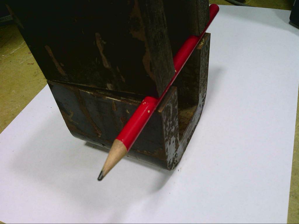 A hypothetical air gap might be say, 0.5mm at the thin side and 2mm at the wide side. Give this a try, Klaus has tested a few of these swinging chokes with great success. Cheers, ĀTony. |
||||
