
|
|
Forum Index : Electronics : 150V 45A MPPT - roll your own
| Author | Message | ||||
| Warpspeed Guru Joined: 09/08/2007 Location: AustraliaPosts: 4406 |
Grant, these Aerosharp chokes are wound silicin steel U cores as you can see in the above picture. They are made from the exact same material as our beloved large inverter toroids, but are wound around a rectangular mandrel, instead of a round mandrel for toroids. These "rectangular toroids" are then sawn in half, and the mating faces ground to a mirror flat finish. This is the right stuff, but its from some unknown Chinese company I have never heard of. https://softmagneticcore.en.made-in-china.com/product/oeQEsIKdfFfg/China-Soft-Iron-Silicon-Steel-Cutting-C-Cores-CD-Cores-for-Transformer-Reactor-Sensor-Mutal-Inductor.html Edited 2020-06-16 10:55 by Warpspeed Cheers, ĀTony. |
||||
| poida Guru Joined: 02/02/2017 Location: AustraliaPosts: 1392 |
Build notes #1: for those of us who will input more than about 85V, we will need to change R6 from 2k7 to something smaller. I suggest the change is to 1K5 if you have it or 1K. R6 is part of Vin voltage divider. It lives about 20mm to the left of the top right screw hole. If you use 1K5, at 150V the Nano will get 4.64V which is nearly maximum input voltage for the ADC. It does not leave a lot of headroom for showing voltages more than 150V. In most cases this will be the best choice, it gives the best resolution when displaying input voltage. I calculate it to be about 6.3 ADC counts per volt in the input of the converter. This means we will only see about +/- 0.2V accuracy at best. If you use 1K resistor for R6, then 150V will produce about 3.12V and have a lot more headroom when the input voltage is higher than 150V. This has 4.3 counts per volt on the input, and it will be a bit worse accuracy. The original 2K7 resistor gives about +/- 0.1V resolution for input voltages up to 90V. The firmware does not use input voltage in it's calculations for maximum power point tracking. It uses the output voltage and output current. wronger than a phone book full of wrong phone numbers |
||||
| poida Guru Joined: 02/02/2017 Location: AustraliaPosts: 1392 |
Here is the "large Aerosharp core". Note the very thin laminations. This is not a 50 Hz transformer's laminations as we know it, Jim. This is really thin silicon iron sheets, that permit it to work at rather higher frequencies than 50 Hz. 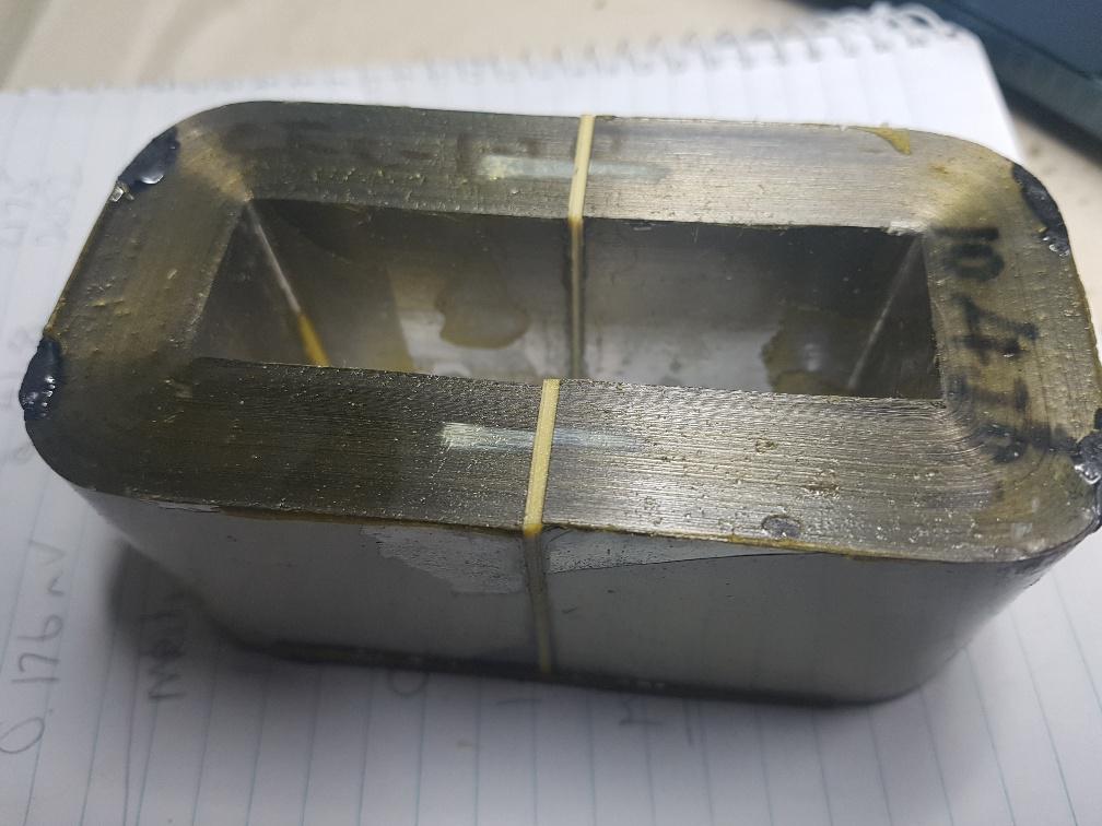 And see the gap, that is very important. No gap means not much use for this project. wronger than a phone book full of wrong phone numbers |
||||
| poida Guru Joined: 02/02/2017 Location: AustraliaPosts: 1392 |
The reason I keep showing how to test inductors is that we need to be able to take something that "might work" and see if it will work. I can't test everything. You all will find something that is a possibility. It is easy to test an inductor. things you need: a 1 Ohm 2500W resistor. the converter power board the converter brainboard a potentiometer The 1 Ohm resistor is easy to make. Get about 6 feet of the 0.9mm galvansied steel wire you can buy from Bunnings, used in the garden. The wire spool is about 50 Meters. Cost about $10 Put 6 feet of this wire around a paving brick or thick bit of MDF or something that will stay below the water line in a bucket of water. Connect 4.5mm2 copper wires to both ends and lead these up to the converter's output terminals. The resistor works perfectly well until the wire rusts down to too thin steel to support the 45 Amps. Then it fails. No biggie. Just make a new one - recall you bought 50 meters of it? Run the code I posted earlier at https://www.thebackshed.com/forum/ViewTopic.php?TID=12027&P=17#147544 calibrate for your current sensors and voltage dividers, and then try an inductor and see how the current goes. I run it up to 2kW output and look at the inductor current. Calibrating this sensor is simple too. You will need a current sensor on the inductor circuit. I use the LEM sensors but the Allegro sensors will work fine. See if it saturates. See what the ripple current is and if it is low enough for the purpose. If anyone want to do this, reply here and I will work you through the process. Calibration means changing 4 lines in the code. Those 4 lines define the calibration. 2 more lines define the current sensor zero offsets. Those are dead simple to setup too. Edited 2020-06-16 20:31 by poida wronger than a phone book full of wrong phone numbers |
||||
| wiseguy Guru Joined: 21/06/2018 Location: AustraliaPosts: 1017 |
Poida, Today I ordered some sets of EE65 ferrites from Neosid @ 11.10 + GST each. 3 sets are about $37 total. On paper they should handle more energy ~10-15% more than two of the EE70 core sets. I am currently designing a 3 stack bobbin using PCB material that will solder together at the edges/seams and our great Chinese friends... to manufacture, 10 bobbins for ~$14 total ($1.40ea) + freight. For those that cant picture what it should look like I have done a quick scribbled sketch which may help. 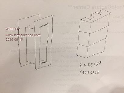 This could be a reasonable cost/performance contender. I have also asked them for a list of readily available lowish cost large sendust cores from their overseas suppliers, for toroidal choke experimentation, to avoid long lead times. So much to do so little time available..... I forgot to add that if the gap say for the centre pair of E's is less than the other two it would perform much like the swing choke, better at lower energies whilst still retaining a high saturation ability. Edited 2020-06-16 21:37 by wiseguy If at first you dont succeed, I suggest you avoid sky diving.... Cheers Mike |
||||
| Warpspeed Guru Joined: 09/08/2007 Location: AustraliaPosts: 4406 |
Another slightly different version of this same idea by Magnetics: https://elnamagnetics.com/wp-content/uploads/library/Magnetics-Documents/Step-gap_E-Core_Swing_Chokes.pdf Stacking a pair of toroids that have very different characteristics may be yet another approach to this. Edited 2020-06-17 09:41 by Warpspeed Cheers, ĀTony. |
||||
| poida Guru Joined: 02/02/2017 Location: AustraliaPosts: 1392 |
More tests. 2 x small, gapped N87(?) E cores 62.6uH, 7 turns. In 107.1V, 20.2A, 2163W Out 48.0V, 42.2A, 2026W, 93.6% 28A ripple. No saturation and a good candidate for the project looks like this:  2 x N27 E70/33/32 E cores with hand crafted 1.5 - 1.6mm gaps. (the $26 a set items from RS Components) 58.4uH with 6.5 turns In 106.8V, 20.1A, 2147W Out 48.0V, 42.0A, 2016W, 93.9% 30A ripple. A bit too high. so I made it with 9 turns. 99.1uH, 9 turns In 106.7V, 20.3A, 2166W Out 48.4V, 41.9A, 2028W, 93.6% 15A ripple. This is a $52 inductor that will work fine at 2500W and 110V input. Give it 9 turns of whatever fits in the gap and you are good to go. 15A ripple at 2000W and 110V is excellent. Now, I built a double with Mark's expensive E cores. 2 x N87 E70/33/32 with I think 0.5mm gaps. The gaps are not big enough but that is what it is. 66.6uH from 6 turns In 106.4V, 20.7A, 2202W Out 49.0V, 42.1A, 2063W, 93.7% 25A ripple. This showed signs of saturation at 2500W but only minor. I would make a bigger gap in both and put more turns in it and then this pair will be good for the project. The cost of these 2 pairs is $100. I still maintain the view that you get 2 pairs of the N27 E70/33/32 from RS, make a 1.5mm gap for both pairs, put 9 turns of something thick through the pair and you will have the inductor you need. It is easy to spend a lot of time trying to save a bit of money. One of my aims with this project is to compile information and resources that will be enough to easily build the 45A mppt controller no matter if you have a lot of parts saved from inverters or if you have to buy things from suppliers. wronger than a phone book full of wrong phone numbers |
||||
renewableMark Guru Joined: 09/12/2017 Location: AustraliaPosts: 1678 |
Hey mate, I dropped off two different types of 9700nh cores one set was this one with no gap. That is the cheaper one, but it's out of stock. The other set was this one They each have a 1mm gap in the centre leg, so 2mm when joined. So what you could do is mix the pairs, or have each set side by side std, so one with no gap and one with 2mm gap. Anyway it's pretty clear the silicon steel cores are far superior. Embrace the dark side and go with them. Cheers Caveman Mark Off grid eastern Melb |
||||
| poida Guru Joined: 02/02/2017 Location: AustraliaPosts: 1392 |
So I used one of each to make two pairs with a gap. Of 1mm as it happens now. Not 0.5mm as I guessed. wronger than a phone book full of wrong phone numbers |
||||
| poida Guru Joined: 02/02/2017 Location: AustraliaPosts: 1392 |
With about 20 extra lines of code, I have now made use of the spare pin available on the brainboard v2 (pin marked "A5") I added a fan control, with user defined turn ON and turn OFF temperatures, taken from the heatsink NTC. This might be good for any builders of this project who will install the charge controller in hot environments. It is also good for people who can't source a big enough heatsink. This spare pin can be used in other ways. As an analog input, for something else you might need. As a digital input, maybe a START/STOP button. A change mode for the LCD data, where we can press a button to run through the stored calibration values, temperature limits, charge voltages etc. What extra functions do you think you would use? Edited 2020-06-18 11:01 by poida wronger than a phone book full of wrong phone numbers |
||||
| renewableMark Guru Joined: 09/12/2017 Location: AustraliaPosts: 1678 |
Maybe try one set of the ungapped next to the other 2mm gapped set, that would be a little like Warps swinging choke wouldn't it? Cheers Caveman Mark Off grid eastern Melb |
||||
Revlac Guru Joined: 31/12/2016 Location: AustraliaPosts: 964 |
Boards arrived today, Thanks Peter.  Cheers Aaron Off The Grid |
||||
| johnmc Senior Member Joined: 21/01/2011 Location: AustraliaPosts: 282 |
PCB's arrived today, many thanks Peter. cheers john johnmc |
||||
| poida Guru Joined: 02/02/2017 Location: AustraliaPosts: 1392 |
Here are the two inductors and how they perform. 110V input, 20kHz pwm, 1 Ohm load. First is two with 1.0mm gap each. Two of the E cores, 6 turns, 66uH the White lines are current at 500,1000,1500,2000,2500W Blue is pwm, Yellow is current. We don't need to know the scale, but it is 0.3V/div and 0.197V/Amp Zero current is the 4th line up from the bottom. 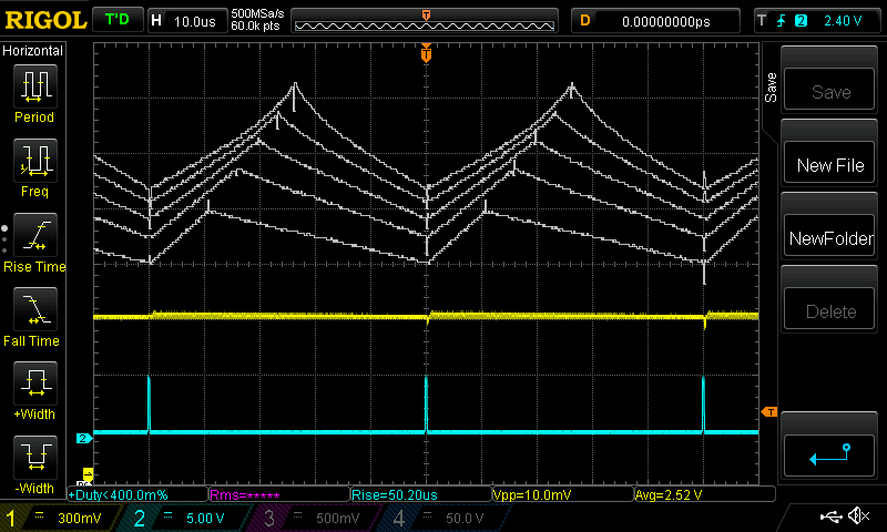 We clearly are seeing the start of saturation at 2500W. but I would be happy to run this inductor in a build of the 45A mppt controller. Next, I undo everything, and make one E core with zero gap and another with 2.0mm gap. Just as you wanted to see. I then put 6 turns around the inner leg, so it's the same as the above test. This gives an inductance of 425.5 uH This would seem to be really much more better-er than anything because it's 425uH and I have shown about 100uH is pretty much spot on. More is better, right? 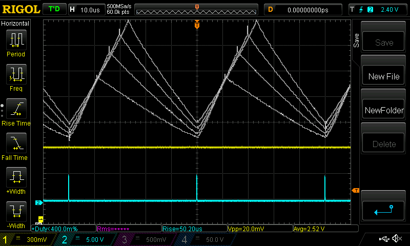 I did not bother going to 2500W, we can see where things are heading already at 2000W. Not good. At 2000W there is a 60Amp swing. What is happening is the zero gap E core saturates with little power, becoming an expensive short circuit, leaving the remaining 2.0mm gap core to just do something already. With only the 2.0mm core and not many turns, we see clearly the result of low inductance. i.e. very steep current traces. This is not in anyway a definitive proof of the worthlessness of Warp's recent comments on the subject. A stepped gap might be quite useful here. I don't know how to built one and test it. So far I am content with a single gap width of something with a suitable permeability. We get a straight line for the current as the voltage is applied to the inductor. This is beer-driven Electronic Engineering research. Lucky there is some in the fridge. Edited 2020-06-19 20:35 by poida wronger than a phone book full of wrong phone numbers |
||||
| renewableMark Guru Joined: 09/12/2017 Location: AustraliaPosts: 1678 |
Thanks for doing that Peter, if you could be bothered, maybe the same test with the set of 2mm gap and that other one of 4mm gap. Only if you are curious though, I'll be using the dark side silicon steel cores. It might be "better-er" Edited 2020-06-19 20:35 by renewableMark Cheers Caveman Mark Off grid eastern Melb |
||||
| Revlac Guru Joined: 31/12/2016 Location: AustraliaPosts: 964 |
I get the impression that it will go to the closest gap first, so if using 2 chokes the need the same gap.. does that seem correct. I can find some silicon steel U cores somewhere in the shed, going to test them when all the parts arrive. Cheers Aaron Off The Grid |
||||
| Solar Mike Guru Joined: 08/02/2015 Location: New ZealandPosts: 1129 |
That stepped gap idea is akin to two cores in parallel but mutually coupled together; the amount of coupling being determined by the ratio of the two gap sizes. The largest gap should be dominant as most of the time there will be largish currents through the core, it is only at very low currents where we want the small gap to have much affect, this to remain in continuous conduction mode. Chomping off bits of the center leg using a dremel diamond cutter is possible, but gets very costly if you get it wrong. Not sure its easily adjustable with ferrite other than using a tapered packing wedge across all 3 core legs and carefully clamping together so it doesnt crack. I would make the smallest gap say 0.2mm and narrow, perhaps 10%, leaving the rest to a wider 1.5-2mm, be cool if it works... May be easier if two cores in series, one with small gap, other large; at least the inductances add up here, just copper losses accumulate. Mike |
||||
| Warpspeed Guru Joined: 09/08/2007 Location: AustraliaPosts: 4406 |
Two sets of ferrite cores with 1.0mm gap is marginal. Just as you say, it is right at the point of going into final terminal saturation. Taking one of those core sets away and increasing the gap to 2.0mm is not going to work. What is left is just far too small, whatever you do. More gap, insufficient inductance, less gap even worse saturation. Your lowest power level is still very high, and will keep the zero gap core set in constant saturation, and it may as well not be there. If you want to make this a fair test, go back to two core sets with 1.0mm gap that you started out with, and add a third core set with a gap that is actually going to work at your lowest power level. Don't know what that might be, but try 0.2mm for a start. So two core sets with 1.0mm gaps, plus one core set with 0.2mm gap for example. Three ferrite core sets is starting to become large and expensive, which just goes to show that ferrite is a less than ideal material for such a high power choke application. Try it with either one Aerosharp core pair suitably tilted, or two Aerosharp core pairs with "suitably" different gaps. Its going to take some testing and experimentation to determine what "suitable" is. But again, I might start out with maybe 1.0mm and 0.2mm as a start, either for the max/min tilt, or for the two different gap spacings of a pair. That is not based on anything more than a wild guess. But the results should indicate what to try next. Cheers, ĀTony. |
||||
| SYM-1 Newbie Joined: 18/10/2019 Location: New ZealandPosts: 40 |
I found some silicon steel cores on alibaba. Can anyone tell me the dimensions required? Persistence is the key |
||||
| poida Guru Joined: 02/02/2017 Location: AustraliaPosts: 1392 |
The one shown in the above post is 15.75mm thick 103mm long 53mm wide 46mm high approx 15.75mm radius at each of 4 corners very thin laminations wronger than a phone book full of wrong phone numbers |
||||
