
|
|
Forum Index : Microcontroller and PC projects : PicoMite Alpha Firmware - a27 onwards - starting on displays
| Author | Message | ||||
| lizby Guru Joined: 17/05/2016 Location: United StatesPosts: 3363 |
Excellent additions. I appreciate the flexibility between program and variable memory. Re GUI, does this mean that 4 GUI controls take 256 bytes, and 5 take 512? Is OPTION MEMORY a persistent option or one which a running program can set to suit its needs? PicoMite, Armmite F4, SensorKits, MMBasic Hardware, Games, etc. on fruitoftheshed |
||||
disco4now Guru Joined: 18/12/2014 Location: AustraliaPosts: 1000 |
PIXEL commands is there. Any change of PIXEL function. Latest F4 Latest H7 FotS |
||||
| lizby Guru Joined: 17/05/2016 Location: United StatesPosts: 3363 |
PicoMite MMBasic Version 5.07.00a36 Copyright 2011-2021 Geoff Graham Copyright 2016-2021 Peter Mather > OPTION SYSTEM SPI GP2,GP3,GP4 > OPTION SDCARD GP5, 10 > OPTION LCDPANEL ILI9341, LANDSCAPE,GP20,GP19,GP18 OPTION TOUCH GP22,GP21 OPTION SYSTEM I2C 14,15 > OPTION RTC AUTO ENABLE > ?date$,time$ 24-06-2021 08:41:51 > memory Program: 0K ( 0%) Program (0 lines) 80K (100%) Library 0K ( 0%) Free RAM: 0K ( 0%) 0 Variables 0K ( 0%) General 112K (100%) Free >> OPTION MEMORY 64,60000 memory Program: 0K ( 0%) Program (0 lines) 58K (100%) Library 1K ( 0%) Free RAM: 0K ( 0%) 0 Variables 1K ( 0%) General 129K (100%) Free > Sweet. PicoMite, Armmite F4, SensorKits, MMBasic Hardware, Games, etc. on fruitoftheshed |
||||
| lizby Guru Joined: 17/05/2016 Location: United StatesPosts: 3363 |
But ... > option list OPTION SDCARD GP5, 10 OPTION SYSTEM SPI GP2,GP3,GP4 OPTION SYSTEM I2C GP10,GP11 OPTION LCDPANEL ILI9341, LANDSCAPE,GP20,GP19,GP18 OPTION RTC AUTO ENABLED OPTION GUI CONTROLS 64 OPTION MEMORY 60160, 100352 OPTION TOUCH GP22,GP21 > EDIT Error : Not enough memory > memory Program: 23K (31%) Program (919 lines) 58K (100%) Library 4294967274K (-31%) Free RAM: 0K ( 0%) 0 Variables 2K ( 1%) General 128K (99%) Free > 23K program size, 128K Free RAM, but "Not enough memory". This is with the program ccpico.bas in the zip file some posts back. UPDATE: I tried again after power cycling: LOAD "ccpico.bas", then F4, and it works. ~ Edited 2021-06-24 22:05 by lizby PicoMite, Armmite F4, SensorKits, MMBasic Hardware, Games, etc. on fruitoftheshed |
||||
| Mixtel90 Guru Joined: 05/10/2019 Location: United KingdomPosts: 7877 |
Using a36 I've not tested it with a program of any size in, but things seem to be working OK. I've set OPTION GUI CONTROLS 39 to use just under 2k OPTION MEMORY is showing 79104, 82688 But, like lizby found, there's a screwy calculation somewhere: Program: 1K ( 1%) Program (13 lines) 77K (100%) Library 4294967295K (-1%) Free RAM: 0K ( 0%) 0 Variables 1K ( 0%) General 112K (100%) Free ILI9341 is sharing display & touch with SD card ok. Clock is updating from DS3231 at boot ok. OPTION AUTORUN 1 is loading & running the digital clock demo from the MicroMite manual. docs update: PicoMite docs a36.zip Edited 2021-06-25 04:01 by Mixtel90 Mick Zilog Inside! nascom.info for Nascom & Gemini Preliminary MMBasic docs & my PCB designs |
||||
| thwill Guru Joined: 16/09/2019 Location: United KingdomPosts: 4303 |
Hello Peter, You've probably considered it already, but could you avoid partitioning the memory in advance (at least between variable memory and GUI controls) by allocating variables counting up from the bottom of the available RAM and GUI controls counting down from the top of the available RAM and then simply report an error if those two pointers ever cross ? Best wishes, Tom Edited 2021-06-25 04:11 by thwill MMBasic for Linux, Game*Mite, CMM2 Welcome Tape, Creaky old text adventures |
||||
| matherp Guru Joined: 11/12/2012 Location: United KingdomPosts: 10250 |
Yes but no - it would be a major rewrite of a lot of Geoff's code All there is an issue in b36 I need to sort and fix (the edit memory bug) so don't waste too much time on it Edited 2021-06-25 04:29 by matherp |
||||
| Mixtel90 Guru Joined: 05/10/2019 Location: United KingdomPosts: 7877 |
Have I understood this correctly? There is a pool of 160k of RAM. We decide how many controls we want: ControlsRAM = <num_of_controls>*52 bytes rounded up to next 256 byte multiple. FreeRAM is 160k - ControlsRAM We can allocate up to 1/2 of FreeRAM as program space, the rest is used for both variables and editing. We could allocate, say, just 20k to the program to get some bigger arrays or something. Mick Zilog Inside! nascom.info for Nascom & Gemini Preliminary MMBasic docs & my PCB designs |
||||
| matherp Guru Joined: 11/12/2012 Location: United KingdomPosts: 10250 |
Perfectly - once its working  Edited 2021-06-25 04:42 by matherp |
||||
| Mixtel90 Guru Joined: 05/10/2019 Location: United KingdomPosts: 7877 |
Well, yeah. :) Mick Zilog Inside! nascom.info for Nascom & Gemini Preliminary MMBasic docs & my PCB designs |
||||
| lizby Guru Joined: 17/05/2016 Location: United StatesPosts: 3363 |
FWIW, here's the pinout I used for the PCBs shown above. This configuration allows 2 SPI, 2 Com ports, 2 I2C ports, 3 ADCs, and a few free pins. Pico 2x20 20x2 Pico # # USB # # I2C0 SDA 1 | 0 3 | 40 VBUS I2C0 SCK 2 | 1 5 | 39 VSYS GND 3 | | 38 GND SPI_SCK 4 | 2 19 | 37 3V3_EN SPI_MOSI 5 | 3 21 | 36 3V3(out) SPI_MISO 6 | 4 21 Pico | 35 ADC_VREF SPI_CS_SD 7 | 5 37 I/O 12 28 | 34 Digital/ADC2 GND 8 | | 33 GND/ADCGND p18 9 | 6 18 22 27 | 32 Digital/ADC1 p24 10 | 7 24 29 26 | 31 Digital/ADC0 COM2:Tx 11 | 8 16 | 30 RUN COM2:Rx 12 | 9 11 36 22 | 29 T_IRQ GND 13 | | 28 GND I2C1 SDA 14 | 10 27 33 21 | 27 T_CS I2C1 SCK 15 | 11 28 15 20 | 26 LCD_D/C (SPI2_MISO) 16 | 12 35 28 19 | 25 LCD_RST p31 17 | 13 31 27 18 | 24 LCD_CS GND 18 | | 23 GND (SPI2_SCK) 19 | 14 40 22 10 | 22 COM1:Rx (SPI2_MOSI) 20 | 15 38 7 8 | 21 COM1:Tx # # USB # # Pico 2x20 20x2 Pico Within the vertical bars are the pico pin numbers (closest to "|") and the pin numbers on the 2x20 expansion port (numbering the same as on the CMM2). PicoMite, Armmite F4, SensorKits, MMBasic Hardware, Games, etc. on fruitoftheshed |
||||
| panky Guru Joined: 02/10/2012 Location: AustraliaPosts: 1114 |
@lizby Pico physical pins 21 and 22, GPIO 8 and 10?? Edited 2021-06-25 09:47 by panky ... almost all of the Maximites, the MicromMites, the MM Extremes, the ArmMites, the PicoMite and loving it! |
||||
| lizby Guru Joined: 17/05/2016 Location: United StatesPosts: 3363 |
You're right--Pico physical pins 21 and 22 should be GP16 and GP17. Thanks. (No effect on the PCBs.) PicoMite, Armmite F4, SensorKits, MMBasic Hardware, Games, etc. on fruitoftheshed |
||||
| led-bloon Senior Member Joined: 21/12/2014 Location: AustraliaPosts: 207 |
@lizby I imported your Eaglecad files into KiCad and it would appear that one track is incomplete. Pin 23 of the 40 pin header (SCK). Then again, I am not a user of these softwares at all, so could be just me! led Miss you George |
||||
| Mixtel90 Guru Joined: 05/10/2019 Location: United KingdomPosts: 7877 |
As things seem to stand at the moment: Yes. 4 controls will fit take 52*4=208 bytes so will fit into the first 256 byte block. 5 controls require 52*5=260 bytes which will overspill into the next block, so will requite 512 bytes to be allocated. If you allocate 9 controls you get the next 4 for free! They will require 52*9=468 bytes. OPTION MEMORY seems to be persistent. If you want to change it you will have to use OPTION MEMORY RESET then reallocate. @matherp Just wondering... Rather than allocate GUI controls from a preset RAM allocation, could they be strings, arrays or even a Csub with the address(es) passed to the GUI handler? I suspect it might not be feasible without severe changes to the original code though. Incidentally - had ARC running yesterday and it seems to work fine. :) Edited 2021-06-25 17:18 by Mixtel90 Mick Zilog Inside! nascom.info for Nascom & Gemini Preliminary MMBasic docs & my PCB designs |
||||
| matherp Guru Joined: 11/12/2012 Location: United KingdomPosts: 10250 |
a37 PicomiteV5.07.00a37.zip NB: file replaced at 10:40 UTC I think I've removed the bug from OPTION MEMORY Full GUI functionality now implemented DISTANCE function now implemented (Take care HR-SR04 need 5V and PicoMite pins are not 5V safe - use a level converter) NB: FLASH commands should work OK independent of MEMORY setting. Flash spacing is always 80K but save and load are based on the setting of the MEMORY option 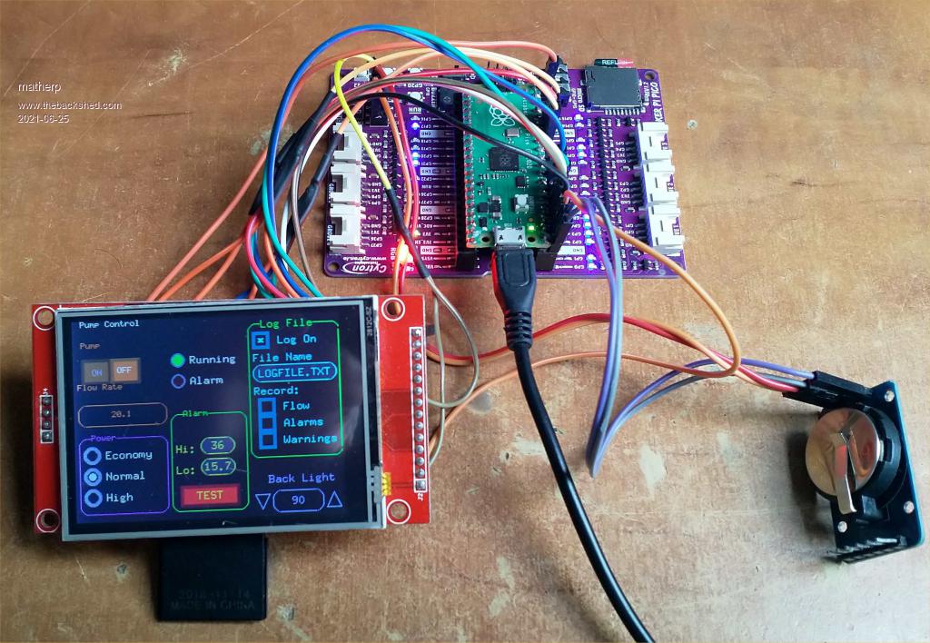 ''''''''''''''''''''''''''''''''''''''''''''''''''''''''''''''''' ' Demonstration program for the Micromite+ ' It does not do anything useful except demo the various controls ' Modified for ILI9341 by Phil23 ' ' Geoff Graham, October 2015 ''''''''''''''''''''''''''''''''''''''''''''''''''''''''''''''''' Option Explicit Dim ledsY Colour RGB(white), RGB(black) ' reference numbers for the controls are defined as constants Const c_head = 1, c_pmp = 2, sw_pmp = 3, c_flow = 4, tb_flow = 5 Const led_run = 6, led_alarm = 7 Const frm_alarm = 20, nbr_hi = 21, nbr_lo = 22, pb_test =23 Const c_hi = 24, c_lo = 25 Const frm_pump = 30, r_econ = 31, r_norm = 32, r_hi = 33 Const frm_log = 40, cb_enabled = 41, c_fname = 42, tb_fname = 43 Const c_log = 44, cb_flow = 45, cb_pwr = 46, cb_warn = 47 Const cb_alarm = 48, c_bright = 49, sb_bright = 50 ' now draw the "Pump Control" display CLS 'setpin 18,dout 'pin(18)=1 GUI Interrupt TouchDown, TouchUp ' display the heading Font 2 : GUI Caption c_head, "Pump Control", 10, 0 Font 2 : GUI Caption c_pmp, "Pump", 10, 25, , RGB(brown) ' now, define and display the controls ' first display the switch Font 2 GUI Switch sw_pmp, "ON|OFF", 10, 45, 70, 30, RGB(white),RGB(brown) CtrlVal(sw_pmp) = 1 ' the flow rate display box Font 2 : GUI Caption c_flow, "Flow Rate", 5, 75,, RGB(brown),0 Font 2 : GUI Displaybox tb_flow, 5, 100, 105, 25 CtrlVal(tb_flow) = "20.1" ' the radio buttons and their frame Font 2 : GUI Frame frm_pump, "Power", 5, 140, 105, 90,RGB(200,20,255) Font 1 GUI Radio r_econ, "Economy", 20, 160, 10, RGB(230, 230, 255) GUI Radio r_norm, "Normal", 20, 185 GUI Radio r_hi, "High", 20, 210 CtrlVal(r_norm) = 1 ' start with the "normal" button selected ' the alarm frame with two number boxes and a push button switch Font 2 : GUI Frame frm_alarm, "Alarm", 115, 115, 90, 115,RGB(green) Font 1 GUI Caption c_hi, "Hi:", 120, 150, LT, RGB(yellow) GUI Numberbox nbr_hi, 150,MM.VPos-6,40,MM.FontHeight+6,RGB(yellow),RGB(64,64,64) GUI Caption c_lo, "Lo:", 120, 175, LT, RGB(yellow),0 GUI Numberbox nbr_lo, 150,MM.VPos-6,40,MM.FontHeight+6,RGB(yellow),RGB(64,64,64) GUI Button pb_test, "TEST", 125, 200, 70, 25,RGB(yellow), RGB(red) CtrlVal(nbr_lo) = 15.7 : CtrlVal(nbr_hi) = 35.5 ' draw the two LEDs Const ledsX = 125, coff = 50 ' define their position ledsY = 50 : GUI LED led_run, "Running", ledsX, ledsY, 8, RGB(green) ledsY = ledsY+25 : GUI LED led_alarm, "Alarm", ledsX, ledsY, 8, RGB(red) CtrlVal(led_run) = 1 ' the switch defaults to on so set the LED on ' the logging frame with check boxes and a text box Colour RGB(cyan), 0 GUI Frame frm_log, "Log File", 210, 10, 110, 160, RGB(green) GUI Checkbox cb_enabled, "Log On", 215, 20, 20, RGB(cyan) GUI Caption c_fname, "File Name", 215, 45 GUI Textbox tb_fname, 215, 60, 100, 20, RGB(cyan), RGB(64,64,64) GUI Caption c_log, "Record:", 215, 85, , RGB(cyan), 0 GUI Checkbox cb_flow, "Flow", 220, 100, 20 GUI Checkbox cb_alarm, "Alarms", 220, 120, 20 GUI Checkbox cb_warn, "Warnings", 220, 140, 20 CtrlVal(cb_enabled) = 1 CtrlVal(tb_fname) = "LOGFILE.TXT" ' define and display the spinbox for controlling the backlight GUI Caption c_bright, "Back Light", 230, 190,,RGB(200,200,255),0 GUI Spinbox sb_bright, 210, 210, 110, 25,,,10, 10, 100 CtrlVal(sb_bright) = 100 ' All the controls have been defined and displayed. At this point ' the program could do some real work but because this is just a ' demo there is nothing to do. So it just sits in a loop. Do : Loop ' the interrupt routine for touch down ' using a select case command it has a different process for each ' control Sub TouchDown Select Case Touch(REF) ' find out the control touched Case cb_enabled ' the enable check box If CtrlVal(cb_enabled) Then GUI Restore c_fname, tb_fname, c_log, cb_flow, cb_alarm, cb_warn Else GUI Disable c_fname, tb_fname, c_log, cb_flow, cb_alarm, cb_warn EndIf Case sb_bright ' the brightness spin box 'BackLight CtrlVal(sb_bright) Case sw_pmp ' the pump on/off switch CtrlVal(led_run) = CtrlVal(sw_pmp) CtrlVal(tb_flow) = Str$(CtrlVal(sw_pmp) * 20.1) CtrlVal(r_norm) = 1 Case pb_test ' the alarm test button CtrlVal(led_alarm) = 1 'GUI beep 250 Case r_econ ' the economy radio button CtrlVal(tb_flow) = Str$(CtrlVal(sw_pmp) * 18.3) Case r_norm ' the normal radio button CtrlVal(tb_flow) = Str$(CtrlVal(sw_pmp) * 20.1) Case r_hi ' the high radio button CtrlVal(tb_flow) = Str$(CtrlVal(sw_pmp) * 23.7) End Select End Sub ' interrupt routine when the touch is removed Sub TouchUp Select Case Touch(LASTREF) ' use the last reference Case pb_test ' was it the test button CtrlVal(led_alarm) = 0 ' turn off the LED End Select End Sub Edited 2021-06-25 20:39 by matherp |
||||
| Solar Mike Guru Joined: 08/02/2015 Location: New ZealandPosts: 1162 |
That looks very nice: Are the PIO state machines available for use in the Picomite basic routines.? Cheers Mike |
||||
| Mixtel90 Guru Joined: 05/10/2019 Location: United KingdomPosts: 7877 |
I don't think Peter has even considered what to do with the state machines yet, Mike. He's been concentrating on making MMBasic work to the proposed spec. :) Mick Zilog Inside! nascom.info for Nascom & Gemini Preliminary MMBasic docs & my PCB designs |
||||
| lizby Guru Joined: 17/05/2016 Location: United StatesPosts: 3363 |
Not just you. Right you are. Just a tiny "air wire" missing. Updated gerbers: picomite_mcp2.3_2021-06-25.zip picomite_1.3_2021-06-25.zip And EagleCad files: PicoMite EagleCad Ver 3.zip Updated pinout: Pico 2x20 20x2 Pico GP# # USB # GP# I2C0 SDA 1 | 0 3 | 40 VBUS I2C0 SCK 2 | 1 5 | 39 VSYS GND 3 | | 38 GND SPI_SCK 4 | 2 19 | 37 3V3_EN SPI_MOSI 5 | 3 21 | 36 3V3(out) SPI_MISO 6 | 4 21 Pico | 35 ADC_VREF SPI_CS_SD 7 | 5 37 I/O 12 28 | 34 Digital/ADC2 GND 8 | | 33 GND/ADCGND p18 9 | 6 18 22 27 | 32 Digital/ADC1 p24 10 | 7 24 29 26 | 31 Digital/ADC0 COM2:Tx 11 | 8 16 | 30 RUN COM2:Rx 12 | 9 11 36 22 | 29 T_IRQ GND 13 | | 28 GND I2C1 SDA 14 | 10 27 33 21 | 27 T_CS I2C1 SCK 15 | 11 28 15 20 | 26 LCD_D/C (SPI2_MISO) 16 | 12 35 28 19 | 25 LCD_RST p31 17 | 13 31 27 18 | 24 LCD_CS GND 18 | | 23 GND (SPI2_SCK) 19 | 14 40 22 17 | 22 COM1:Rx (SPI2_MOSI) 20 | 15 38 7 16 | 21 COM1:Tx GP# # # GP# Pico 2x20 20x2 Pico PicoMite on FruitOfTheShed ~ Edited 2021-06-25 23:24 by lizby PicoMite, Armmite F4, SensorKits, MMBasic Hardware, Games, etc. on fruitoftheshed |
||||
| lizby Guru Joined: 17/05/2016 Location: United StatesPosts: 3363 |
Regarding the ILI9488, is there any reason not to simply cut off the MISO pin on the LCD module? PicoMite, Armmite F4, SensorKits, MMBasic Hardware, Games, etc. on fruitoftheshed |
||||
| The Back Shed's forum code is written, and hosted, in Australia. | © JAQ Software 2025 |
