Home Page
  Home  |  Contents  |  Forum
Print


Build a encapsulated load resistor. Page 1 | 2 | 3 | 4

Back to Page 1

To make the resistors more compact to fit the resistors were bent around a piece of 30mm tube to form a horse shoe. To aid in the bending two short bits of ½” tube were slide over the resistors and then hand bent around the 30mm tube held in the vice.


A mount is made by punching holes through a piece of sheet metal and inserting the resistors into the holes. The resistors was then silver soldered into place.

I think the outer casing of the elements is a form of stainless steel and silver solders very easy if clean. There is no risk of damaging the resistor with heat, if heat is only applied to the outside casing. (they do glow red in your oven)

TESTING AND ADJUSTING THE RESISTORS

Connect one resistor to the required voltage, with a suitable amp meter in the line. Switch on power and record the amp meter reading. Switch off power. If the resistor amps is lower than desired this is good. It is easy to increase the amps per resistor by simply stretching/pulling more nichrome wire out from the inside of the mineral core.. Pull out 50mm (stretched) of wire and move the supply wire back in close to the resistor and retest the amps. Repeat the process to the desired amps is obtained. Repeat procedure for other resistors. This way all resistors can be adjusted to be close to equal to one another.

As can be seen in the photo above the nichrome wire outside the element will glow red in operation (6.4 amps in this case). This was a less than desired situation as it generated heat out near the terminal.

To reduce the resistance outside the element a short piece of 1mm dia. Copper wire was inserted into the ceramic core 5-10 mm and the nichrome wire wound around it tightly out to the terminal. This reduced the heat here greatly and gave support to the nichrome wire as it gets very soft when its hot.

In an earlier element made, some of the mineral core was scratched out, and the ends packed with Teflon tape (standard plumber thread tape) this worked well and gave better support to the copper wire and formed an insulator out to the end which handled the temperature very well. Pink Teflon tape used

Note:- the pink tape is a much thicker tape than the white plumbing tape. Either will work fine just need more layers with the white.

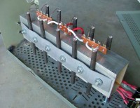
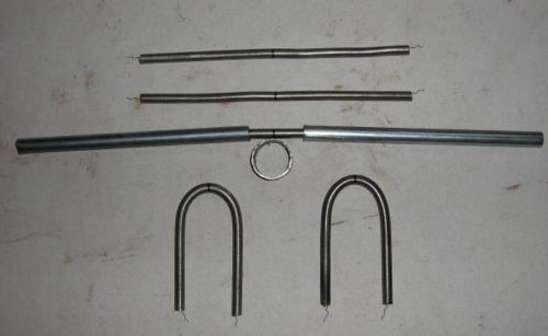
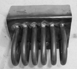
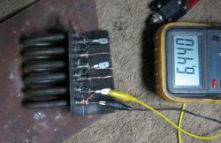
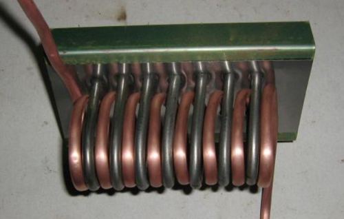
WATER HEATERS

There is no reason why an element for a water heater cannot be made in the same way. I could find no difference between the elements used in an oven compared to the element used in a dishwasher to heat the water and then air dry the dishes after. I have not tested an element in a submerged situation but see no reason why it will not work faultlessly.

One word of WARNING is not to get water or moisture into the ceramic core as this will cause the resistor to fail. Should by accident you get moisture in the mineral core than the moisture should be removed or dried out before applying power to the resistor. To remove moisture, heat the resistor outer casing from the centre working outwards to the ends using a gas flame or likes of, till the outer casing is a dull red in colour and no more steam or moisture is emitted. Allow to cool and use as per normal.

WITH HEAT EXCHANGER

After having worked out the basic procedure for fabricating resistors and seeing the amount of energy emitted as heat, I pondered how it could be best put to use. ( as everyone else undoubtedly has done). The biggest problem was where the load resistors are located on average, is not normally where there is a lot of use for heating. As this is a project in working, the thought of incorporating a heat exchanger for water was adapted. I realize that efficiency is low and most likely no better than 20%, but was done just to show the concept.

Next Page

© TheBackShed 2011