|
|
|
|
 Print Print
|
|
|
|
| Gills Anemometer. |
Page 1 | 2 |
 Back to Part 1: Gills Anemometer Logger Back to Part 1: Gills Anemometer Logger
Cup Type
The anemometer head was made from the drive motor of a computer hard disc drive, three plastic toy juggling balls, 3 short lengths of welders braising rod, and a nut, plus of course the all important UGN3503U hall sensor.
Procedure:
Prise open the motor and dispose of the stator replacing it with a steel block cut from a nut and the hall sensor. Then reassemble ensuring the sensor is clear of the magnetic ring. Cut thread to both ends of each of the100mm to 110mm long braising rods. Tap 3 holes to suit in a thick HDD platter spacer. To this fit the rods and balls that have been cut in half to make the cups. Balance using heavy copper wire wound around the lightest rod spiders. Mount to a suitable pole or spar for calibration. Fit the pole or spar to your vehicle and on a still day, with a laptop connected, drive down a smooth private road noting the vehicle speed and anemometer reading.
I found Glenn’s PicLog excellent for calibration as the conversion factor is able to be changed without reprogramming the PicAXE.
The cogging reported by others using a hall sensor is almost unnoticeable in the units I have built. It is normal to see it turning in a draught when there appeared to be no air movement at all.
On one installation the head was connected by well over 60meters of cable to the anemometer control unit. Reduction of the control units trim pot setting from the normal 1m Ohm was needed to offset the line loss. The reduction was by about 5 turns of the available 25 so reasonably long cable runs are possible. |
|
|
|
|
|
|
|
|
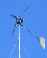
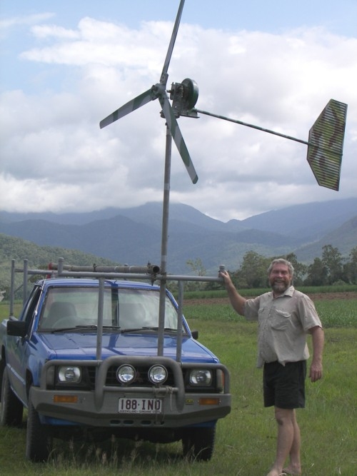
Fan Type.
A fan type head has also been used and may suit some installations. As the signal method chosen was the same as the cup type a similar motor modification is used. Unfortunately, whilst easier to modify the fan than make a cup type, the fan type needs a yaw bearing and tail to track the wind and slip rings for power and signal wires. Its smaller swept area is more susceptible to cogging though its revs are 10 times greater giving better resolution. I use the fan type for bench testing as it can be blown by another computer fan over many days and is quite compact.
Gill. |
|

|

|
|
Just a note from the site owner. Gill passed away on the 15th May 2009. He contributed a great deal to this site and he will be fondly remembered by myself and the members of our forum community.
Rest in peace mate.
|
|
|
|
|
|
© TheBackShed 2011
|