
|
|
Forum Index : Electronics : Nano Power Inverter - Roll Your Own Style
| Author | Message | ||||
| poida Guru Joined: 02/02/2017 Location: AustraliaPosts: 1432 |
I found out what is happening. I needed to load the broken code and see for myself. how it all falls down: on boot, code in setup() is executed. This includes setting oen = 0 (inverter commanded to STOP) and it calls init_vars() which in our case sets sst = 100 other stuff is completed then loop() is called repeatedly. Within loop() a test is made, is sst > 0, if so, pull D5 high, else pull it low. This test does not care if the inverter is supposed to be enabled, that is, checking if oen = 1 And so we have D5 pulled high for a period of time EVEN THOUGH WE COMMANDED THE INVERTER OFF in the first code executed during boot. This is not good. I reproduced both of the results you show above. A detail on the 3rd test you show when you set sst = 200 You pulled D8 high just before sst had enough time to count down to zero, to cause D5 to then go low, so sst counted down from 200 to maybe 50, you pulled D8 high and then sst started to count up again. D5 always stayed high since sst was always > 0 The experiments we are doing with changes to sst ALONE are not good. Unexpected inverter running will result. If you want to continue with this, you need to add a bit more code to check for oen = 1 AND sst > 0 before pulling D5 (Gate drive enable) high it will look like this: if (sst <= 0) // once fully stopped, no more changes to sst needed { sst = 0; cbi(PORTD,5); // pull IR2184 shutdown LOW to disable gate drive output } else { if (oen == 1) sbi(PORTD,5); // pull it HIGH, to enable output } I attach a new version with this fix, to allow you to use any value sst within 0 to 200 (I do not want you to use larger values due to the risk of a sharp transition from bang/bang to PID) nano_1_v7_no_bessel_smooth_stop_1K_steps.zip I needed to know the DC supply voltage so as to calculate the value of "pwr" and so estimate a safe maximum for sst experiments. 31.2V AC RMS at your setpoint means 44.1V peak to peak Let's say you are testing at 50V DC, that means pwr will be about 44.1 / 50 = 0.88 So for a smooth transition to PID, pwr needs to get to 0.88 With the 1000 step firmware, that means sst must increase for 880 steps When we start the inverter, pwr is initialised to 0.0 and it will only be changed by steps of 1/1000 either up or down. IF we start sst at 200, it will NOT increase 880 steps, only 800 steps since the max value for it is 1000. PID will switch over with a significant error, about 80 times as large as it could be if we let pwr get to 0.88 IF we have sst = 100, then after the remaining 900 steps, pwr will be hovering around 0.88 and so we get a smooth changeover. This 0.88 is calculated from an assumed DC supply of 50V. what voltage are you testing at anyway? (This code is just for Mike to fiddle with. I very much prefer everyone else to use earlier, unmolested code nano_1_v7_no_bessel) wronger than a phone book full of wrong phone numbers |
||||
| wiseguy Guru Joined: 21/06/2018 Location: AustraliaPosts: 1206 |
Thanks for looking into the code and finding out what was going on - I suspected we had some asynchronous stuff going on and we shifted something whilst no one was looking.... What I wanted to achieve was not just shortening the count up but at the SST = 100, I wanted the power level to have stepped up to power level = 100/1000. ie Ramp-up sine does not begin at zero but steps in at the SST = ? value. When I had looked at the code I saw that further down there was a power level routine that appeared to start at 1/1000 I suspect it needs to start at the 100/1000 but still incrementing at 1/1000 steps from there. That was going to be my next experiments in the code if it needed more tweaks and that sst =100 did not give me the 10% power increment start. But I broke it before I got that far. I am not worried at the relatively low energy step jump at the start - yes I know they are my Mosfets..... I have a theory that if the transformer is soft stopped we could probably start the power level at even up to 50% without a loud "boing" thing happening but I was going to get there starting from ~ 10% and slowly get larger from there. My DC bench testing is usually done at 46 volts. Real life running values is from 53V down to 44V, with most of the running time at ~ 48 - 51 Volts. I prefer to do most experiments where if there is a Vfb issue the output voltage wont get much higher than ~ 245V. Reminds me of that saying, "Life sucks then you die" haha Edited 2022-07-12 10:21 by wiseguy If at first you dont succeed, I suggest you avoid sky diving.... Cheers Mike |
||||
| poida Guru Joined: 02/02/2017 Location: AustraliaPosts: 1432 |
46 V DC supply 31.2V AC RMS at your setpoint means 44.1V peak to peak pwr needs to get to 44.1 / 46 or 0.96 to achieve your AC output setpoint 0.96 (This explains a few things now.) So that means 960 of the 1000 steps are needed just to get to 235V AC output because pwr is initialised at 0.0 at the start of every soft start. you can experiment with different soft start ramps of course. They are your FETs.. The change over to PID will not be very kind at all to your FETs if there is a large difference in pwr's value from 0.96 when change over occurs. look for three things below to change void init_vars() // called prior to setting oen = 1, as well as from setup() { ICR1 = PPWM; lv_stopped = 0; sst = 0; // slow start counter 0 - 1001. v1low = 1; // half wave output flag, 0 or 1 pcount = 0; // counter for sine wave lookup table uf = 0; // set to 1 to enable AC output voltage feedback code to execute pwr = 0.0; // PWM duty cycle analog, 0.0 to 1.0 // added this vpwr = (int)((float)PPWM * pwr); //in place of //vpwr= 0; // integer equivalent of pwr, 0 to PPWM You can start the ramp up at any value by changing sst you can also start the sine wave modulation amplitude at any value by changing pwr pwr needs to be between 0.0 and 0.99 sst can be from 0 to 200 or more. Changing these things invalidates your warranty. wronger than a phone book full of wrong phone numbers |
||||
| wiseguy Guru Joined: 21/06/2018 Location: AustraliaPosts: 1206 |
Peter the inverter is working again and I am using the latest code unmodified. My pioneering spirit to play with the code has lost some of its appeal for the moment. I realised this when despite checking the operation of the Power PCB on all legs of the bridge and powering the bridge from a low energy power supply starting from 1V and increasing it to 30VDC, it then still took me quite a few minutes to get up the courage to hit it with 46V and nothing to limit current anymore. It wasn't spectacular at all, it still grunted at me and I grunted back and said thank you. Sometime in a few days I will play with the code some more but first I will put a small series resistor on the transformer primary until I am confident that there are no glitches lurking waiting for an opportunity to take out more FETs. Thanks for the fiddle friendly code too. �If I wanted to try a really slow ramp can I just replace all the 1000's with 2000 and the 1001's with 2001 ? Edited 2022-07-12 19:48 by wiseguy If at first you dont succeed, I suggest you avoid sky diving.... Cheers Mike |
||||
| poida Guru Joined: 02/02/2017 Location: AustraliaPosts: 1432 |
yes, you change the numbers just like I showed in a previous post. 1000 to 2000 means find 1000 ->2000 find 1001 ->2001 find 1000.0 ->2000.0 see the earlier post for accurate instructions. wronger than a phone book full of wrong phone numbers |
||||
| wiseguy Guru Joined: 21/06/2018 Location: AustraliaPosts: 1206 |
Just wanted to make sure that with much bigger numbers it all still holds true, thanks for the confirmation. If at first you dont succeed, I suggest you avoid sky diving.... Cheers Mike |
||||
| wiseguy Guru Joined: 21/06/2018 Location: AustraliaPosts: 1206 |
Starting to get a second wind with my inverter progress (or lack of it...). I recently bought two 3kW Aerosharps for $25 each as I am still trying to avoid a full toroidal rewind. My plan was to consider using two transformers that could be driven in parallel for plenty of grunt. Ideally though at night for conservation it would be good to only have the one transformer with its associated magnetising current instead of two. I have decided to abandon the two smaller transformers that I have been using to date as despite them working ok they are still a bit undersized for the eventual loads I want to be able to drive. I am confident that the grunt issue will be resolved when I get the right recipe for my HF choke which appeared to have a bit too much inductance. I also want to be able to work on the inverter and simply swap chokes etc without it all being jammed into too small an enclosure and thus any changes became a major exercise. So a new chassis and layout is also in the works. Eventually I will have a wheeled trolley with nano inverter, battery storage, battery charger, grid feed inverter and a few other bits all in one easily moved and easily worked on trolley. The Aerosharp transformers looked identical except one winding was black and white wires, the other was black and off white - a slight tan colour. The label describes the transformer as 230VAC for the black and white and 250V for the Blue & Red winding. One could be forgiven to expect that the black and white winding was for the mains input but this is not so, they are from the inverter drive, the Red and Blue 250V winding is for the mains L & N connection. Initially I had hoped the mains winding would be the inner winding and I could simply remove the outer winding and slap a new primary on it and job done. However as the voltages on the existing two windings are fairly close perhaps they could be put in parallel for an ultra low loss mains winding? I worked out the volts per turn by throwing 10 turns through the core and driving the primary with 100V and was able to determine that the primary had 212T and the secondary had 195 turns. All I had to do was add 17T to the 195T and they would both be 212T. So far so good. Whilst the transformer was already on the bench, I placed the second unit next to it and wired the primaries in parallel, joined the secondary blacks and whites together and slowly wound up the Variac. I noted the power consumption was slightly more than the addition of the 2 idling currents, so I placed an amp clamp on one of the secondary wires and noted that there was ~ 1.1A flowing ! So I disconnected the bridged secondary and there was ~ a 0.9V difference. I had already established on the first transformer that 1 turn was ~ 1.13V - what gives, something doesn't add up !! So transformer 2 behaves slightly different, I re did the turns evaluation and the second transformer has 215T on the primary and 197T on the secondary. The only possible way to drive them in parallel is to add 3 turns to the first transformer primary (212), 20 turns to its secondary(195) then they are both at 215T and then add 18 turns to the second transformers secondary (197) and voila now we have 4 x 215T windings. Now simply add a 27T primary to both units and job done. I am less than ecstatic at this whole proposition, so I am considering buying yet a third 3kW Aerosharp to find out what arbitrary primary and secondary windings it has. Would it be the same as one of the two I have or will there be a third variant ? Just as a note of interest, the first transformer with the 212T primary at 240V it draws ~ 12.5W and at 220V it is ~ 9.7W. The second transformer with the 215T primary draws 9.72W at 240V and at 210V (not a typo) it is ~ 7W. These are quite different values, the second transformer idling power at 240V is only ~77% of the first unit. This leads me to my next thoughts that maybe if inverter power generation requirement (overnight) for longish periods is less than 50W (an arbitrary guess figure) the voltage could be reduced to 210 or 220VAC to reduce wasted magnetising power and as soon as power is greater than 50W it could revert to 230/240, whatever is normal for a given set up. When there are a few overcast days and perhaps not a huge storage bank, every bit saved helps. I of course am considering employing a complicated (over complicated?) setup where if the power requirements of the load exceed 3 or 4kW then the second transformer is switched in parallel to assist with energy throughput and minimise losses and heat build up. At this stage I dont think a separate power H bridge driver from a common controller is required as I think the one H bridge with the 16 x HY5608s should cope ok. Last comment obviously I would use the transformer with the lowest magnetising current for the overnight economy and switching the other lossier unit when I need some bulk power. I would be pleased to receive comments, suggestions, criticisms or advice about what to do with transformer quandry I seem to be facing. Edited 2023-03-28 23:18 by wiseguy If at first you dont succeed, I suggest you avoid sky diving.... Cheers Mike |
||||
| rogerdw Guru Joined: 22/10/2019 Location: AustraliaPosts: 905 |
Hi Mike, I think I can point to some info on this. So far I have only seen two different types for the 3500W Aerosharp ... Eaglerise and Hefei Ecu-Tamura. I reckon the one you showed me the other night with the yellow label was an Eaglerise. The cores for each are quite different size, with the Eaglerise being 205mm OD, 100mm ID and 70mm High. The Hefei Ecu-Tamura is 185mm OD, 100mm ID and 70mm High. See pictures and discussion here ... The Eaglerise core is a lot rougher than the Hefei Ecu-Tamura ... in fact it is made up of lots and lots of short pieces. Mine looked all rough and rusty almost. The windings were a lot more jumbled and twisted also. In contrast, the Hefei Ecu-Tamura core was very neat and tidy and made up of one continuous strip with no joins. I know this because I used two of them to add to the cores I used for my big Warpverter core. See here for some closeups ... and you can see some of the overlapping joins. They didn't even bother to butt them together. PLEASE TAKE NOTE ... in the posts at that time I MIXED UP THE TRANSFORMER NAMES ...  Haxby kindly corrected me and this was the conclusion here ... Cheers, Roger |
||||
| rogerdw Guru Joined: 22/10/2019 Location: AustraliaPosts: 905 |
Mike, Warpspeed suggested I measure the idling power loss of each of those cores while they were bare. I reported the results back then but figure it may be helpful to paste (the corrected name version) in here. Wound both with 20 turns. #1Tx is the rough looking Eaglerise Electric CSArea of 37.1 sq/cm 16.47V RMS gives a result of 1 Tesla on the calculator. .8235V/Turn Fed winding with 16.47V RMS and showed reading of .47A Am I correct in saying that VA = 7.74 ? #2Tx is the much better looking Hefei ECU-Tamura toroid CSArea of 35 sq/cm 15.54V RMS gives a result of 1 Tesla on the calculator. .777V/Turn Fed winding with 15.54V RMS and showed reading of .36A VA = 5.59 Cheers, Roger |
||||
| Murphy's friend Guru Joined: 04/10/2019 Location: AustraliaPosts: 671 |
Mike, you might want to think about that all on one a single trolley idea. My dual stack inverter (2 x 3KW cores) weighs around 50kg. Adding a decent size GTI and battery charger would more than double this weight. But my battery trolley with 20KW of lithium batteries is over 150kg. Combining all that would make for a very heavy trolley, heavy steel sections and beefy (expensive) castors. If you are considering LA batteries then it will be much heavier still, beside I think it's not a good idea to have electronics and big (LA) batteries in close proximity. Your other (over complicated  ) idea of switching two cores in parallel, or not as power demands, is something I would not consider at all. For a start, you need two heavy primaries to be switched as well, which complexity and expense would surely negate any saving from miniscule idle current gains. ) idea of switching two cores in parallel, or not as power demands, is something I would not consider at all. For a start, you need two heavy primaries to be switched as well, which complexity and expense would surely negate any saving from miniscule idle current gains.< 20W all up idle power for a 5+KW inverter is much better than many very expensive commercial units. Put your money toward decent batteries and solar capacity and you win in the long term. To give you an idea what works here: I had 5KW of panels and 20KW of battery capacity which (with similar power demand you quote) drained the bank down to 70% of its capacity overnight, usually. The battery bank was back full by mid morning in Summer and late morning in Winter. IMO 16 HY4008's are good for 5+KW, no problem here with that. |
||||
| wiseguy Guru Joined: 21/06/2018 Location: AustraliaPosts: 1206 |
Thanks Roger & Klaus currently at work, will answer in full tonight. I bought another 3kW Aerosharp at lunch time so will report on that too. Roger both of the first two cores look identical I am sure it is the same supplier - will post all pics and results of new tranny hopefully late tonight - I hope it is not the other variant.... that I dont need ! If at first you dont succeed, I suggest you avoid sky diving.... Cheers Mike |
||||
| pd-- Senior Member Joined: 11/12/2020 Location: AustraliaPosts: 122 |
I am unwinding the secondary on a Eaglerise 2KW core at the moment it is made out of 4 lengths of wire wound 2 in hand separately over all dimensions 200mm dia 60 hole 75 high 16.5 kg |
||||
| wiseguy Guru Joined: 21/06/2018 Location: AustraliaPosts: 1206 |
Some good news, I dodged a bullet, the third Aerosharp is the same transformer as the first. the second Aerosharp is not identical just nearly, it measures 210mm across. Aerosharps 1 & 3 measured 220mm across. Heights of all 3 were the same ~ 90mm. Some pictures below No 1) Production Date 6/4/10 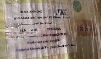 No 2) Production Date 24/2/11  No 3) Production Date 15/3/10 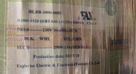 I was just lucky that 1 and 3 were close together in manuf. dates All inverters have the exact same model number on their stickers. The only downside is the idling current of unit 3 is ~ 13.5W, unit 1 is ~ 12W. The odd one out with the slightly smaller diameter was the lowest at ~ 9.5W So I now have ~ 39 electrolytics, 16 Hall effect current sensors, 9 x large C-cores 3 large boxes with BIG heatsinks and crap all over the place - so many circuit boards screws and cables - anyone want some stuff ? Roger the picture of your Eaglerise Transformer dated 28/3/10 was made 13 days after my number 3 and 9 days before my number 1. I will post this before I lose it....... If at first you dont succeed, I suggest you avoid sky diving.... Cheers Mike |
||||
| rogerdw Guru Joined: 22/10/2019 Location: AustraliaPosts: 905 |
Oh well, it still gives you options ... and there's more metal in the core of these toroids than the other type. It is amazing just how much hardware is in each of these units and it's difficult to decide what to keep and what to turf out. Certainly the caps have value ... the C-cores ... the heatsinks etc etc ... and all those shiny stainless screws. Now I'm kicking myself for not including the footprint of these particular current sensors on my mppt boards coz I've got a heap too. Surprising the dates on our transformers being so close, probably from a big batch sent to Adelaide. I couldn't find the details of the other one of those I used. Cheers, Roger |
||||
Bryan1 Guru Joined: 22/02/2006 Location: AustraliaPosts: 1458 |
make sure you save some goodies for me mate as those board connectors aint far away now |
||||
| wiseguy Guru Joined: 21/06/2018 Location: AustraliaPosts: 1206 |
Klaus, let me assure you I have thought (agonised?) about the trolley idea a lot ! My application and direction is rather specific at the moment for at least the next year or two. I have the Sirius 3.6kWH storage unit which weighs ~ 65kG & will be on the bottom shelf, it measures 55cm x 65cm x 20cm. Next shelf up will be the Battery Charger and some other "stuff". In my application all the items will be wired together and the trolley location can be easily changed. The GTI will be mounted vertically at one end of the trolley and the nano inverter will be on the top shelf. The trolley frame which is being currently built will be ~ 800mm high ~600 deep and ~ 650mm wide It is just for proof of concept at this stage and my intention is not to disconnect from the grid yet as I can still get a return for my excess power. Today at around noon we were only generating ~ 8.5kW and we were consuming a whole ~450W. I intend to AC couple my battery storage to feed my house requirement if the roof solar is offline or not generating enough for our needs (think night or heavy cloud) but not to feed any of the battery storage to the street grid at all. When solar resumes before feeding 1W back to the grid I will fully recharge the Battery unit first. I estimate the total weight will be ~ 150kG + the trolley weight. I already have some surplus castors that should easily handle that weight. 13.5W from 7pm until 10am is ~ 200WH not much for 20kwH (~1%) but for 3.6kWH (~6%) If I use a second inverter power stage driven by the same controller there is no need to switch the second primary I just enable the second power stage drive, but that needs to first have the second transformer degaussed before connecting it directly in parallel with the mains output of first transformer. Piece of cake! Making this work is quite straightforward for me but I wont rush into it, I tend to play devils advocate in my head for quite a while before starting something. Also for now, I am only planning to use the nano inverter if the grid actually fails as it will need a few switches to be thrown first (disconnect grid join L1,L2,L3 in parallel etc. The conserving power is more academic at this stage and if and when I get some bulk storage and disconnect from the grid (and gas) then I may not care as much anymore, I just like stuff running as efficient as possible if its just a matter of a bit of time and a few more bits when I already have probably 95% of what I need in my "stuff". The real fun will begin when I use the nano inverter to commutate the GTI's and toss the grid for good - when I start to receive power bills again which with the reducing tariff is probably not too far off, I will get more incentive to finally disconnect. I haven't had to pay a cent for power since Dec 1999, for an initial outlay of ~ $9K. In summer on a typical day we generate ~ 85kWH/day, 13.5KW of panels & 10kWGTI. It paid for itself ~ 1 year ago. If at first you dont succeed, I suggest you avoid sky diving.... Cheers Mike |
||||
| wiseguy Guru Joined: 21/06/2018 Location: AustraliaPosts: 1206 |
Roger thanks for the extra information you looked up and posted for me. I found when working out the idling power of a transformer you need to measure the true power with an accurate energy meter. The unloaded transformer will have inductive reactance and even if the current is measured with an RMS meter because of the phase shift between the voltage and current it will not give the correct result. The analogy is a bit easier to see if you put a capacitor say 10u across the mains and monitor the current, amps can be seen flowing but the true energy meter might show just a watt or so, when the sum of the current times voltage would be a much bigger number. The transformer is a similar scenario but the phase shift is different by nearly 180 degrees. However monitoring the primary or secondary current when the inverter is running will lead you a bit astray as it will show amps flowing but the battery will be supplying much less than that. The battery volts and current supplied to the inverter can be simply multiplied to determine transformer idling current (dont forget to minus the solenoid/relay, DC fan and nano controller etc). The load current on the secondary of the transformer must be measured after the filter capacitor for accurate results. The inverter transformer circulating current is from the smoothing capacitor we place across the transformer secondary to integrate the HF Sine PWM back into a smooth sinewave. It causes more current to be flowing back and forth than what we actually feed it. Edited 2023-03-30 23:24 by wiseguy If at first you dont succeed, I suggest you avoid sky diving.... Cheers Mike |
||||
| Murphy's friend Guru Joined: 04/10/2019 Location: AustraliaPosts: 671 |
Mike, I did not realise that you have a quite small battery (compared to mine which is now 25KWh), so your all on one trolley idea now makes more sense than my set up: one large (20KWh) and one medium (5KWh) battery trolley one good size (6KW) inverter and a bigger warp inverter one 3.6KW GTI on the wall one 2KW GTI on the wall two MPPT chargers on the wall (one is a spare) plus various electronics to monitor cell voltages, solar string currents, battery voltage sensing to turn off GTI when full etc. Since there is always way more solar (and battery) power available than I'm using I do not really worry much about idling currents. I think all those electronics, displays & meters here draw their fair share of standby power too.  |
||||
| The Back Shed's forum code is written, and hosted, in Australia. | © JAQ Software 2025 |
