
|
|
Forum Index : Microcontroller and PC projects : General purpose I2C IO module
| Author | Message | ||||
| Mixtel90 Guru Joined: 05/10/2019 Location: United KingdomPosts: 7865 |
Not a problem. I'll finish checking them then post the Gerbers. Mick Zilog Inside! nascom.info for Nascom & Gemini Preliminary MMBasic docs & my PCB designs |
||||
| Turbo46 Guru Joined: 24/12/2017 Location: AustraliaPosts: 1639 |
Looking forward to it. I dug out my old MODBUS slave and from what I can work out it should work on your board as is. A daughter board connected via the O/I connector could hold the interface to the outside world. Bill Keep safe. Live long and prosper. |
||||
| Volhout Guru Joined: 05/03/2018 Location: NetherlandsPosts: 5058 |
@mixtel90, I did not investigate the MX170 datasheet, but when there is a chance of connecting the modbus UART RTS pin to a GPIO, then use that GPIO for the DE signal. In that case the UART itself controls the RS485 data direction and not software. The signal needs an inverter in that case (simple 2N7002 and a pullup resistor will do, fast enough). Volhout PicomiteVGA PETSCII ROBOTS |
||||
| Turbo46 Guru Joined: 24/12/2017 Location: AustraliaPosts: 1639 |
@Volhout and mixtel90, The DE pin is pin 7. If DE is not specified in the COMSPEC then it can be toggled under program control so that it does not need inverting. Works for me. Bill Keep safe. Live long and prosper. |
||||
| Mixtel90 Guru Joined: 05/10/2019 Location: United KingdomPosts: 7865 |
I meant to put the inverter back - there's plenty of board space now. In this world of mosfets it's time we used the humble TUN again. :) (Do Elektor still use TUP, TUN, DUG, DUS?) Incidentally, I've just received two more of the 90x70x28 cases and these boards don't fit the VGA mini or these boards (yet). The outside dimensions are the same, but internally the posts are different. Also, the end panels are slightly smaller and won't take the PCB end plates that I made for the VGA mini! As a minimum I'm going to have to do something with the corners (probably notch instead of drill). The constructor may have to cut the pcb mounting posts down (fiddly). The height of the posts is very important when you want to get VGA and PS/2 connectors in as there isn't much wiggle room vertically. There are probably a few Chinese manufacturers making very similar cases and it's pot luck what you end up with. Mick Zilog Inside! nascom.info for Nascom & Gemini Preliminary MMBasic docs & my PCB designs |
||||
| Volhout Guru Joined: 05/03/2018 Location: NetherlandsPosts: 5058 |
Hi Bill, It is fine that it works for you, but this code forces a turn around time of up to 20ms (where at 2ms is standard at 19200 baud, 3.5ms at 9600 baud). May very well be this works in practice, but that is why I proposed to use the RTS pin. Then the turn around time is minimal, and not determined by some fixed number. Volhout PicomiteVGA PETSCII ROBOTS |
||||
| Turbo46 Guru Joined: 24/12/2017 Location: AustraliaPosts: 1639 |
Two points 1. The 20ms can't be changed? Is it likely that a new message will be sent by the Master in that time? I don't think so. The Master will have a time out period much greater than 20mS surely. The delay does not affect the time it takes the slave to respond. 2. The pause is no longer needed anyway because Geoff has since fixed it so the LOF is now true when the final character has been sent. Do you really see it as a deal breaker? Bill Keep safe. Live long and prosper. |
||||
| Mixtel90 Guru Joined: 05/10/2019 Location: United KingdomPosts: 7865 |
I've put the DE inverter back now as it costs virtually nothing. I like that system, it's elegant and neatly supported in MMBasic. :) I've added suitable pads/links so it's also optional. The PCB should fit either case now, although end panels still need sorting out. I've also moved chip pins 17 & 18 to the 21 & 22 positions on the connector. This means that there are still usable IO pins in those positions, even if the pin numbers are wrong. It also means that the missing pins are SCL, SDA, IRQ and 7, only 7 of which would normally have been used as a conventional IO pin. The pin 7 connector position now has a solder blob link to connect it to the actual pin 7. This is to allow the board to run as a free-standing 28-pin controller board without using the DE control, so no RS-485. It might be useful for something. It opens up the possibilities of using COM1 for TX/RX/GND comms. I've supported using an optional LM4040 voltage reference for Analogue Power (pin 28). This can be the High reference voltage for analogue measurements on the MX170, but I'm not sure if the Micromite firmware supports this. It doesn't appear to in the 5.05.03 manual. It doesn't matter much as the chip is running from a regulated 3V3 supply anyway. Edited 2022-01-11 22:58 by Mixtel90 Mick Zilog Inside! nascom.info for Nascom & Gemini Preliminary MMBasic docs & my PCB designs |
||||
| Mixtel90 Guru Joined: 05/10/2019 Location: United KingdomPosts: 7865 |
Big day. :) Piccies and Gerbers. 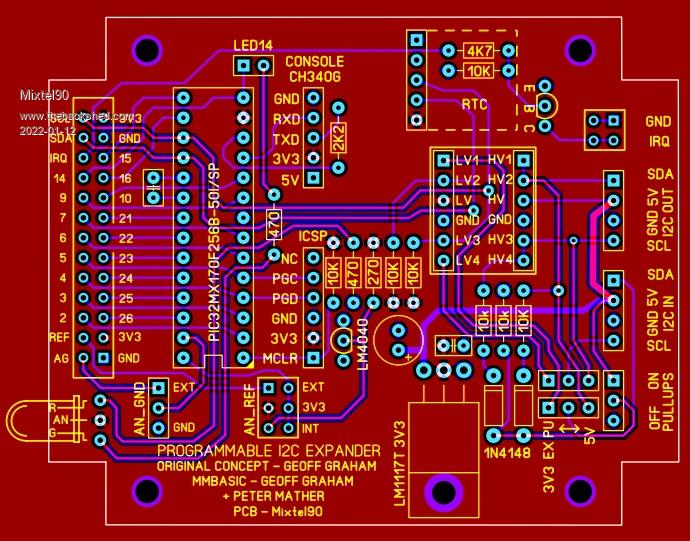 Micromite I2C expander.zip ------------------- 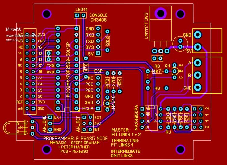 Micromite 485 node.zip Mick Zilog Inside! nascom.info for Nascom & Gemini Preliminary MMBasic docs & my PCB designs |
||||
| lizby Guru Joined: 17/05/2016 Location: United StatesPosts: 3358 |
Thanks for this. Five blue PCBs ordered from JLCPCB for $6.40US, slow boat shipping to Florida. How amazing is that? I don't yet have a specific use, but nice to see Geoff's idea implemented. With a picomite, functionality seems to approach the F4, but with the possibility of VGA output to a big screen. PicoMite, Armmite F4, SensorKits, MMBasic Hardware, Games, etc. on fruitoftheshed |
||||
| Turbo46 Guru Joined: 24/12/2017 Location: AustraliaPosts: 1639 |
Thanks Mick, They look good  Is there any chance that you can post a rear view and circuit please. I just may have to get some. Grumpy Bill Keep safe. Live long and prosper. |
||||
| flasherror Senior Member Joined: 07/01/2019 Location: United StatesPosts: 159 |
Does the RS485 driver have RX/TX LEDs so can see activity? Not seeing any LEDs... Also, is there any cost advantage to using discrete RS485 components as opposed to layout for a "ready to go" RS485 module? Would like to see schematic if available. Edited 2022-01-12 10:14 by flasherror |
||||
| Turbo46 Guru Joined: 24/12/2017 Location: AustraliaPosts: 1639 |
+1 I'm interested as to what you mean by 'discrete RS485 components'? Bill Keep safe. Live long and prosper. |
||||
| Turbo46 Guru Joined: 24/12/2017 Location: AustraliaPosts: 1639 |
@Mixtel90, While you are on a roll... What about a daughter board? I'm thinking of a board, same size, matching holes for spacers. - Female connector to match the I/O connector with pads to connect to. - Matching terminals for power plus maybe an extra for 12 volts or whatever. - A row of terminals along the same side for I/O connections. - A sea of holes between for building an O/I interface. - Suitable for both I2C and RS485 boards. - Plenty of grunt in the 3.3v supply to power this board. Cons: - Probably won't fit in your box. - Maybe not room for a lot of interface circuitry. Bill Keep safe. Live long and prosper. |
||||
| Turbo46 Guru Joined: 24/12/2017 Location: AustraliaPosts: 1639 |
Not true, he has fixed it so that the CLOSE #n command will wait for the last character to be sent before actually closing. A PAUSE is still required for the DE pin in my program. The pause time could be calculated by using the baud rate as I have done in a later version of my Slave program. I don't know how the DE pin when specified in the COMSPEC works. See Bill Keep safe. Live long and prosper. |
||||
| Mixtel90 Guru Joined: 05/10/2019 Location: United KingdomPosts: 7865 |
Updated circuit diagrams to follow. I'm one of the naughty ones because I do the PCB first then do the schematic from that... ;) There are no specific TX/RX LEDs. There is a single bi-colour red/green LED. Normally red is "power on" and Green is via a link LED14 to pin 14 so it is under user control. You could remove the ground end of the resistor for the red led and connect it to a pin to put that under user control too if you so wished. There is no RS485 module. It does use a RS484 transceiver chip, but so would a module. The I2C version uses a level shifter module, is that causing confusion? I've no idea about how DE works either. However, I assume that, as it's inverted, it might be under hardware control as Geoff could have corrected it in firmware otherwise. @Bill Which board would you like a rear view of? I've been considering a "high power" IO box. Same IO connector but linked by a ribbon cable. My idea is that you could have two or three stacked on top of one another, perhaps a couple of relays in one, 4 opto-isolated inputs in another. You get the idea. Links would decide on which pin they were allocated to, perhaps with a choice of 3 for each type of box. Please note: I've referred to these modules as an IO Extender and a RS485 Node. The I2C Extender is intended to be, literally, IO extension to any MMBasic platform using I2C. That's why the modules loop through and are short range. It can also run as a stand-alone Micromite by changing the firmware. The RS485 Node can be a RS485 master or slave. You could link, say, three together and use switches on the master inputs to control outputs on the slaves. The terminating resistors let you set the system up appropriately. The range is *far* greater using these, but at the moment no MMBasic platforms are specifically designed to work with RS485. (Yes, I'm thinking about it... :) ) . Edited 2022-01-12 18:20 by Mixtel90 Mick Zilog Inside! nascom.info for Nascom & Gemini Preliminary MMBasic docs & my PCB designs |
||||
| Turbo46 Guru Joined: 24/12/2017 Location: AustraliaPosts: 1639 |
@Mick, I'm mainly interested in the RS485 unit. I just would like to see the schematic and both front and rear views to verify the design (no offence meant). That was part of my life in my working days. I think it suits my Slave program, or the program can be mad to suit it. I suspect you're right about the DE pin. I respect your decision to make whatever you want for I/O interface board(s). If I can justify the cost of buying a copy of SL6 to myself, then maybe I can have a go at it. Bill Keep safe. Live long and prosper. |
||||
| Mixtel90 Guru Joined: 05/10/2019 Location: United KingdomPosts: 7865 |
I must admit, I wasn't sure about getting SL6. You have to bear in mind that it isn't a full featured PCB design package - and you aren't paying for that. For simple boards it seems to be fine, and the test probe facility is excellent for finding problems in your design. The learning curve is shallower than a full package and, IMHO, more suitable to occasional use where you don't have to keep re-learning stuff whenever you come to use it! Try the demo - it won't save or do anything useful, but it gives you an idea of the facilities and what the help file is like. I'll sort out schematics and rear views. Probably later today. Mick Zilog Inside! nascom.info for Nascom & Gemini Preliminary MMBasic docs & my PCB designs |
||||
| Turbo46 Guru Joined: 24/12/2017 Location: AustraliaPosts: 1639 |
I have tried the demo briefly and I have been using Diptrace but find it very difficult to set board dimensions and hole positions. Dr Google didn't help really either. Bill Keep safe. Live long and prosper. |
||||
| Mixtel90 Guru Joined: 05/10/2019 Location: United KingdomPosts: 7865 |
The circuit of the RS485 version is pretty simple really. COM1 on the Micromite is connected directly to the MAX485 chip. Pin 7 (DE) is connected to both /RE and DE on the MAX485 via an inverting transistor as pin 7 is normally high, going low during transmit. (Thinks... I should perhaps have included a highish value resistor to turn the transistor on so that the system is in RX mode if the Micromite IO isn't initialised.) Mick Zilog Inside! nascom.info for Nascom & Gemini Preliminary MMBasic docs & my PCB designs |
||||
| The Back Shed's forum code is written, and hosted, in Australia. | © JAQ Software 2025 |
