
|
|
Forum Index : Microcontroller and PC projects : General purpose I2C IO module
| Author | Message | ||||
| Mixtel90 Guru Joined: 05/10/2019 Location: United KingdomPosts: 7865 |
Nah... 20mA current loop so that you can put a load of them on the same loop as your teleprinter. :) HC-12 is *far* too new for me. lol Apparently you can split those resistors over the loop and it's recommended that you split them over two places as a minimum, using 1k at both ends of the loop. It makes sure that the data lines stay balanced, even if nodes are removed. I've not seen anything about using such high values - the idea is to get about 200mV across the terminator. Mick Zilog Inside! nascom.info for Nascom & Gemini Preliminary MMBasic docs & my PCB designs |
||||
| Turbo46 Guru Joined: 24/12/2017 Location: AustraliaPosts: 1639 |
Yes, that makes sense (not the teleprinter part  ) )Bill Keep safe. Live long and prosper. |
||||
| flasherror Senior Member Joined: 07/01/2019 Location: United StatesPosts: 159 |
Seconding this. This might be easy to implement as not much board space required (module can hang offboard so only a 5-pin 0.1" connector required). Connections: 5V, GND, TX, RX, and optionally any available I/O for SET pin control (reuse RS485 DE pin as SET. Tradeoff is RS485 and HC12 both can't be used together so either one or the other) I did this for HC12 on an Arduino: 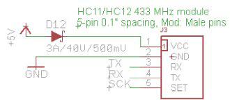 SCK is any I/O but can be the RS485 DE pin (wouldn't use it as RS485 enable but treat it as a general output and manually toggle in code if needed). The diode is for reducing Vcc to module if often transmitting but might not be needed if only occasionally transmitting. No level conversion needed since micromite Pin 21(TX)/22(RX) are 5v tolerant. Edited 2022-01-15 11:34 by flasherror |
||||
| Mixtel90 Guru Joined: 05/10/2019 Location: United KingdomPosts: 7865 |
I'm serious about keeping the modules in the 90x70x28 boxes and having them working with the SSD1963 adapter. They are a family - anything else is something different. :) There *may* be problems with the antenna in the module box. It would have to be external as you can't get it away from the PCB. I wouldn't be happy with the HC12 on the SSD1963 adapter. It's designed to be soldered down, probably with a groundplane on the other side of the pcb, and I just haven't got the space. It would end up hanging in mid air. I'll do pcb designs if you want, but I won't build them or give any guarantee that they'll work at all. Mick Zilog Inside! nascom.info for Nascom & Gemini Preliminary MMBasic docs & my PCB designs |
||||
| Mixtel90 Guru Joined: 05/10/2019 Location: United KingdomPosts: 7865 |
Erm.... 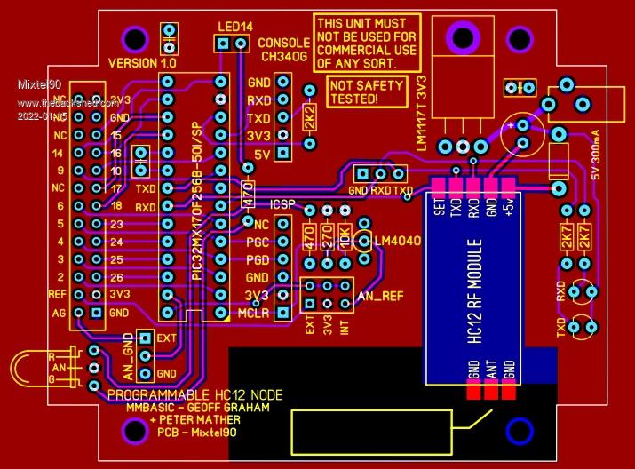 Mick Zilog Inside! nascom.info for Nascom & Gemini Preliminary MMBasic docs & my PCB designs |
||||
| flasherror Senior Member Joined: 07/01/2019 Location: United StatesPosts: 159 |
I was thinking: put the 5-pin HC12 header connector on the RS485 version (near an side panel end for the enclosure?) so that user could populate it assuming don't mind the module sticking out a bit. In any case the common HC12 module has the antenna sticking out so no need to deal with the antenna RF black magic bits like impedance matching etc. It could also be used as a TTL serial port expansion to other devices (TX/RX) and might be useful. The HC12 module connector is 0.1"/2.54mm spacing and so a male header (straight or right angle) would fit nicely. Edited 2022-01-16 02:03 by flasherror |
||||
| Mixtel90 Guru Joined: 05/10/2019 Location: United KingdomPosts: 7865 |
Doesn't fit my ideas for the module series I want. Having odd bits sticking out of the case just doesn't fit. These are designed to be cased and the RS485 module has no spare space along the back anyway. I can find very little *detail* on the HC12 modules. Only the longer blue one (with the spring antenna supplied loose) seems to have a manual - or any info at all. Also, no-one appears to stock the black one at present. The blue module can have header pins fitted, five at one end and a single one near the other. That looks reasonably good for mechanical stability and it will fit easily in the module and on the SSD1963 adapter. Another alternative is to make the HC12 an I2C device. Perhaps with a Micromite to do the processing. A simple command language could then control it from any I2C system. Basically it would be a semi-intelligent modem. Edited 2022-01-16 04:03 by Mixtel90 Mick Zilog Inside! nascom.info for Nascom & Gemini Preliminary MMBasic docs & my PCB designs |
||||
| flasherror Senior Member Joined: 07/01/2019 Location: United StatesPosts: 159 |
English translated manual found on the back shed: http://www.thebackshed.com/docregister/Files/18/HC-12%20v2.3C.pdf (Thanks to Robert for the translation/manual. Is v2.3c the most recent?) Also see https://www.thebackshed.com/forum/ViewTopic.php?TID=8246 for config utility for programming module settings (channel etc). This module has a STM8 microcontroller that interfaces between the host and the RF chip so the picomite/micromite host could implement any other functionality on top of it. Note however that the radio link is not reliable (i.e. chars may be dropped) unlike a TCP/IP connection so a truly reliable link will require checksum/CRC and retry etc. Edited 2022-01-16 07:48 by flasherror |
||||
| Mixtel90 Guru Joined: 05/10/2019 Location: United KingdomPosts: 7865 |
First link, all I see is "Welocme to the home of Calacom". :( The software is of no interest to me - I won't be writing it. :) Mick Zilog Inside! nascom.info for Nascom & Gemini Preliminary MMBasic docs & my PCB designs |
||||
| Turbo46 Guru Joined: 24/12/2017 Location: AustraliaPosts: 1639 |
Check out the 'Doc register' under 'Micromite MMBasic Library(s)' on the Home page of this forum. Grogster had a long post regarding fake and genuine HC-12 here too. See this one too. Bill Keep safe. Live long and prosper. |
||||
| flasherror Senior Member Joined: 07/01/2019 Location: United StatesPosts: 159 |
? I have no idea why the link doesn't work. Copy and paste https://www.thebackshed.com/docregister/Files/18/HC-12%20v2.3C.pdf and see if it works |
||||
| Mixtel90 Guru Joined: 05/10/2019 Location: United KingdomPosts: 7865 |
That worked, thanks. :) The manual I previously found was this one. which is labelled version 1.18 and shows a slightly different version. Looks like I have to rethink the RXD LED as the output from the HC12 can't drive one, apparently. Both manuals agree on essential stuff like voltages, header positions & dimensions so that's enough for me. As far as the pcb designs go it almost certainly doesn't matter whether you use official HC12 modules or fakes/clones providing you use the same sort together. Just don't mix them. Of course, if the firmware is different then that's a whole new ballgame and might equally apply to different revisions of the official modules. Mick Zilog Inside! nascom.info for Nascom & Gemini Preliminary MMBasic docs & my PCB designs |
||||
| flasherror Senior Member Joined: 07/01/2019 Location: United StatesPosts: 159 |
Glad you got the PDF. I believe the limited drive is due to the 1K series resistors which are probably there to allow 5V UART compatibility without level conversion, but that's my guess. Now check out https://www.electrodragon.com/w/EY-40 and https://www.electrodragon.com/w/images/0/05/EY-40_English_manual.pdf This is another radio module with a 6-pin 2.0mm header that is inexpensive (and the physically compatible LC12S radio module which has the same pinout is even cheaper - check ebay for pricing "lc12s 2.4g"). Might want to layout for this module as well if you're doing header pins for HC12. The JDY40 could be next to the HC12 connector to allow user to populate the radio module of their choice. I would put the headers in a straight column to conserve space and ensure that only one module can be used at a time. Edited 2022-01-17 00:09 by flasherror |
||||
| Mixtel90 Guru Joined: 05/10/2019 Location: United KingdomPosts: 7865 |
That looks an interesting little module. 8 IO thrown in for free. :) I've just got sidetracked off these again... Many moons ago I started designing & building a lab power supply using a Micromite & ILI9341 for the instrumentation (not control - that's pure analogue). Interesting design, using a trailing edge switcher (from an old design I found in a magazine) to control the voltage on the reservoir capacitor so that there's never more than 5V across the series pass transistor. I'd previously attempted to make PCBs for it at home (single sided) but I've not been able to get decent boards so it went on the back burner. Anyway, now I've got SL6 and some experience with it I decided to lay out the main control board again using that, as the board area is similar to 100x100mm in area but rectangular. I've done the layout now and I'm at the checking stage. Yet another piling up for JLC. :) Mick Zilog Inside! nascom.info for Nascom & Gemini Preliminary MMBasic docs & my PCB designs |
||||
| flasherror Senior Member Joined: 07/01/2019 Location: United StatesPosts: 159 |
...and when you get back to it also take a look at www.ebyte.com radio modules. Most have a 7-pin 0.1"/2.54mm header and a variety of modules are available for specialized purposes (wireless UART, MODBUS replacement, LoRa etc). Some even feature full duplex radio communication, see https://www.ebyte.com/en/product-view-news.html?id=1648 One E34 module: https://www.ebyte.com/en/product-view-news.html?id=146 PDF manual with dimensions/pinout: https://www.ebyte.com/en/downpdf.aspx?id=146 Implementing a header for these would have some interesting possibilities. Edited 2022-01-19 00:15 by flasherror |
||||
| Mixtel90 Guru Joined: 05/10/2019 Location: United KingdomPosts: 7865 |
I'm doing ONE version to take the HC12 and the EY-40. That's it. I looked at the possibility of having the ESP8266-01S as well, but it got silly as I can't have any backplane close to the antenna on any of the versions, and adding more connectors means that some will end up underneath RF sensitive bits of others. PCB space is at a premium on both the SSD1963 adapter and the IO modules so that's it for the wireless types. I included the EY-40 as it raises the possibility of having an 8-port SMD module without the Micromite in it. Also, it's a local system, being at 2.4GHz. Micromite HC12 node 10.zip My idea for the last module in the series (as far as I'm concerned) will have a female connector on it and will plug directly into the male connector of any of the other modules. It will be another sea-of-holes unit so the user can add lights, switches etc. The already designed sea-of-holes unit can do a similar thing, but would be connected via ribbon cable so a few modules could be stacked vertically with all IO at the back. Edited 2022-01-19 00:59 by Mixtel90 Mick Zilog Inside! nascom.info for Nascom & Gemini Preliminary MMBasic docs & my PCB designs |
||||
| lizby Guru Joined: 17/05/2016 Location: United StatesPosts: 3358 |
My preference now for adding an ESP-01 is to use this module, which takes just 4 pins, including 5V instead of 3V3, and reduces the number of components needed on your main board. I know, though, that this doesn't fit in with your desire to keep everything within the box you are designing for. PicoMite, Armmite F4, SensorKits, MMBasic Hardware, Games, etc. on fruitoftheshed |
||||
| Mixtel90 Guru Joined: 05/10/2019 Location: United KingdomPosts: 7865 |
With added ESP goodness: 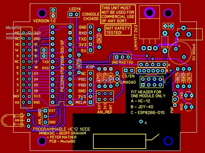 The ESP supply voltage is wrong, I know. :) . Edited 2022-01-19 06:11 by Mixtel90 Mick Zilog Inside! nascom.info for Nascom & Gemini Preliminary MMBasic docs & my PCB designs |
||||
| Turbo46 Guru Joined: 24/12/2017 Location: AustraliaPosts: 1639 |
Hi Mick, You have gone quiet on these boards for a while. I would like to order a couple of them when they are complete. When do you think you may be able to get back to them? Bill Keep safe. Live long and prosper. |
||||
| Mixtel90 Guru Joined: 05/10/2019 Location: United KingdomPosts: 7865 |
I got diverted. Like you do. :) I had a problem with my chosen boxes so I've been making mods to my VGA mini to get it to fit other boxes (probably). I want to order several types of boards this time - and hopefully save on the postage! Then I had another look at the SSD1963 adapters and I've been designing a new backpack board for it. :) There's also been a little tweaking to the IO adapters too, so it's all still on the boil. lol Mick Zilog Inside! nascom.info for Nascom & Gemini Preliminary MMBasic docs & my PCB designs |
||||
| The Back Shed's forum code is written, and hosted, in Australia. | © JAQ Software 2025 |
