 |
|
|
|
Site Navigation
Projects & Information
»General Information»Wind turbine Projects »The F&P Smartdrive »Electronic projects »Microcontroller projects »Miscellaneous Kits & Parts
»Basicly Natural Pty Ltd»PVC & Aluminium blades »Scale model farm windmills »Price Watch Discussion Forums
Handy Links
»Wind»Solar »Electric Vehicles »Electronics »Micro Controllers »General Interrest About TheBackShed Getting Started Privacy Policy Simple Windmill/Solar controller |
|
||||||||||||||||
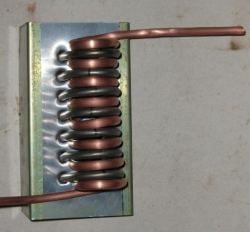
ELEMENT CHOICE There is an endless selection in the choice of elements you might choose to modify, the best ones are what you have or get for free. If I had a choice I would look for the longest in length with as little bends in it as possible. The longer elements with lower wattage ratings appear to have the heavier gauge in nichrome wire, being easier to work with. One element not tried but would think it to be a good source, is the element used in the Simpson clothes dryers and most likely other brands. They are a round ring of about 600mm dia, giving around 2mtrs of element. Worth a try if you have one!! ( I threw a heap out 6 months ago ) The elements used for the project was one I found in the shed from a dishwasher and the others purchased second hand for $2.00 each at a junk yard (oven elements). If removing the elements from a discarded stove then take a bunch of the wire used in the stove, as it has high temperature insulation and most times a female spade terminal on the end. Great for wiring the resistors up with ( and its low cost ). Even if the elements were to be purchased new at a guess of $50.00 each, it would still be cost effective considering some of the other choices. I much prefer low cost or free, as there is nothing to loose and lots to gain.
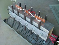
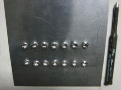
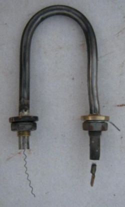
This resistor to the left was made from a submerged element water heater. The mounting end was removed from the original element and reattached with silver solder to a cut down section of element to show it is able to be done. Please note :- This project was only constructed to show what can be done, and has only been tested in simulation from a transformer and not tested in a field application. I see no reason why it will not preform the same if used in a RE field situation. Watts of energy lost in resistors = heat, and no matter how the energy is dispersed the same amount of heat will be generated, weather it is over 1 resistor or spread across 10 resistors the combined heat will be the same.
I welcome any input to this project and any feed back from someone who has used modified encapsulated elements before, or anyone who constructs one from information given above. hope it helps.
Happy Tinkering. From Pete (Downwind). |
|||||||||||||||||
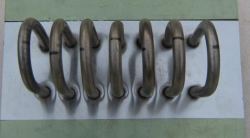
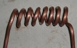
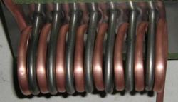
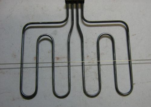
 The element above has 2 x 1200 watt (240v) elements in it, and would yield 6 x pre made hoops if cut on the line made by the rod resting on top. At a guess this would give 6 workable resistors of around 5 amp at 29 volts or about 150 watts each.