|
|
|
|
 Print Print
|
|
|
|
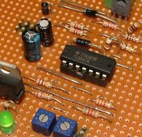
A simple charge controller suitable for wind or solar applications. Uses a TL-084 Op Amp, automotive spotlight relay and a handful of other components. The same circuit could also be used as a low voltage cut off to disconnect your battery before its fully discharged. Suitable for 12 and 24v operation.
The controller uses two trimpots to set a low and high switching voltage. When the applied voltage ( battery ) exceeds the high voltage setting, a relay is turned on. The relay will remain on until the applied voltage drops below the low voltage setting.
For a typical windmill or solar charging application, using a 12v battery, the high trimpot could be set at 15 volts, and the low trimpot could be set at 12 volts. The source ( windmill / solar panel ) is connected to the battery through the relay's normally closed contacts. When the battery voltage reaches 15 volts, the controller will energise the relay, switching the contact and diverting the source into a dump load ( dump loads are not required for solar panels, but are a must for wind generators ).
When the battery voltage drops to 12v, as preset by the low trimpot, the controller will release the relay, reconnecting the source to the battery. |
|
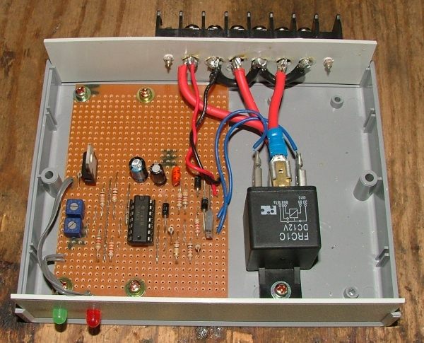
There are two LED's, one indicates power, and the other lights up when the relay is energised. The second LED I've called the Dump On led, as it indicates the source is connected to the dump load instead of the battery.
To set up the charge controller, you will need a variable power supply and volt meter to measure its output voltage.
- Turn the Low trimpot to min (ccw) and the High trimpot to max (cw).
- Attach the variable power supply and adjust its voltage to upper charging voltage limit, eg 15v.
- Turn high side pot down until the LED lights up and the relay clicks in.
- Adjust the power supply to lower limit, eg 12v.
- Adjust low trimpot till relay drops out.
- Now raise and lower the voltage, checking the relay clicks in and out correctly.
- Finished.
The circuit below is for a typical 12v battery. The trimpots have a range from approx 11.5 to 18 volts.
For 24v operation, change R1 from 10k to 22k. This will give the trimpots a range of approx 21 to 32 volts. You would also need to use a 24v relay.
The circuit is based on the TL084 quad op amp. Other OpAmps could be used but this would mean a different veroboard layout and resistor values.
I designed the circuit with the help of CircuitMaker 2000, a circuit simulator. The veroboard was made with Paintshop Pro, and old favourite of mine.
Veroboard Layout.
|
|
Circuit diagram. 12v version.
| Parts List |
| Semiconductors |
|
Capacitors. ( Higher voltage can be substituted ) |
| 1 |
TL-084 Op Amp IC |
|
1 |
100uf 35v electrolytic |
| 1 |
78L08 voltage reg ( or a LM7808 will do ) |
|
1 |
10uf x 16v electrolytic |
| 2 |
1N4004 diode |
|
1 |
0.1 cap Green cap or similar |
| 1 |
1N4001 diode ( or an extra IN4004 will do ) |
|
|
|
| 2 |
LED's colour of your choice |
|
Resistors ( all 1/4 watt or higher ) |
| 1 |
BD139 transistor. |
|
1 |
12k |
| |
|
|
3 |
1k |
| Micalenous |
|
2 |
10k |
| |
Relay with contacts capable of switching
your dump load current. |
|
1 |
3.3k |
| |
IC Socket, Terminal strip, Veroboard, Case, Etc |
|
1 |
8.2k |
| |
|
|
1 |
100k |
| |
|
|
2 |
4.7k |
| |
|
|
1 |
2.2k |
| |
|
|
2 |
10k trimpots ( use multi-turn trimpots if you can ) |
|
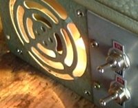
My finished controller.
Adding a pre-regulator.
| What about higher voltages, like 32 or 48 volts? The 7805 voltage regulator wont handle voltages much over 30 volts, so we need to add a pre-regulator if we want to use voltages over 30 volts on our controller. The circuit shown to the right will regulate higher voltages down to a voltage that's safe to feed into the charge controller. Any N channel power MOSFET will work, so long as its rated voltage is higher than the supply voltage. Choose a zener voltage between 16 and 28 volts, depending on your relays coil voltage, the MOSFET has a gate threshold voltage around 3 to 4 volts, so we subtract this from our zener voltage to get the output voltage. eg, a 16 volt zener will give us a 12v to 13v output, a 28 volt zener will give us about 24 volts. For R1 a 10k to 20k resistor should work, we want to pass a few milliamps throught the zener to keep it regulating. C1 and C2 are to filter the supply voltage and stop any unexepected oscillating on the output. 10uF should be enough. |
|
An example of a 48v to 12v regulator.
The MOSFET will need a heatsink. The MOSFET in this example is dropping 36 volts. If we are passing 1 amp, then thats 36 watts ( volts x amps ) the MOSFET needs to dissipate. 36 watts is a lot of power for the small metal tab on the MOSFET to radiate, and without a heatsink attached it would burn out within a few seconds. |
 |
On the controller circuit, R1 will need to be connected to the input of this pre-regulator. Also R1 would need to be about 27k for 32 volts and 39k for 48 volts.
Note: I havn't tested these changes, some experimentation may be needed.
Thanks to Warpspeed for the circuit - http://www.thebackshed.com/forum/forum_posts.asp?TID=4732&PN=1
Further reading.....
|
|
|
© TheBackShed 2011
|