Guru
Joined: 02/02/2017
Location: AustraliaPosts: 1432
| Posted: 01:29am 07 Mar 2017 |
It's become clear to me I need to start a new topic.
In it I will show what I have found, some puzzles that have me completely stumped and hopefully we can put some miscellaneous talk of bits and pieces of our home brew inverters here. I did not want to go off topic and hyjack Tinker's topic.
Contents:
Part 1: Primary Winding Inductors
Part 2: Mains sync
Part 3: Output waveform wiggles
Part 4: Closely watched mosfet gate voltages
Part 5: Experiments with the control loop
Part 6: transformer resonance and a look at primary winding current
Part 7: Primary current waveforms with different inductors plus efficiency calculations
Part 9: Air core inductor possible or am I on drugs..
Part 10: sizing the inverter for my particular requirements and efficiency concerns
Part 11: how does the PWM thing work? Just the basic idea..
Part 12: EG8010 variable output frequency
Part 13: Phase locked loop control with Arduino Uno and Due
Part 14: EG8010 Tfb signal behaviour
Part 15: When 47uH is not the same as 47uH
Part 16: BYO clock for the EG8010
Part 17: That Powerjack I bought. It has a primary choke.
Part 18: primary current during transients
Part 19: examining EG8010 pulse width modulation
Part 20: where the wobbles come from
Part 21: Change over from street to inverter and vice versa
Part 22: Resonant frequency of the toriod/primary choke/secondary winding capacitor
Part 23 examining output waveform shape as SPWM varies and as AC output frequency varies
Part 24: thermal thoughts
Part 25: How I log, process and view the data from my solar power system
Part 25: generator waveforms (from the cheap Chinese 2 stroke genny)
Part 26: A closer look at MOSFET gate voltages during switching
Part 27: Why we make them big and beefy. (Inverters, that is)
Part 28: Gate drive on Madness's power board. This uses on board transistor totem pole drive
I have built a home made inverter using an Arduino microcontroller to drive the mosfet bridge. (more info later..)
Part 1: Primary Winding Inductors
I have been looking at the primary winding inductor lately.
I bought a ferrite E core from RS, based on what other people have used around and about.
I used one of these
http://au.rs-online.com/web/p/transformer-ferrite-cores/6479345/
and have wound 3 1/2 turns. I firmly glued both halves of the E core together
to stop the noise.
The specs show it's AL value is 7900 uH/Turns squared
Oztules and others use 3 or so turns on these things and when I measure the result
with my core and the LCR meter I get 94uH.
This is close to the theoretical value:
7900 uH * 3.5 *3.5 = 96.8uH
So far so good.
I also have a large common mode choke taken out of a 1500VA Aerosharp grid tie inverter. I unwound a lot of the winding to leave 13 turns and 50uH.
Using this inductor I get a much cleaner output waveform compared with the ferrite E core. Why?
I built an inductor tester, similar to what is shown here:
http://ludens.cl/Electron/lmeter/lmeter.html
but instead using an Arduino to create the short duty cycle pulses.
My current shunt is a 2 cm length of copper wire.
It's simple to derive the inductance, just use the simple formula
L (inductance) = (Time x supply volts)/(rise in Amps)

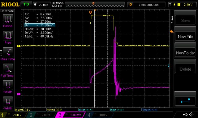
Yellow trace is gate drive for the mosfet.
From the above we see time = 20.8us, supply is 10V from the bench PS and amps is the millivolts of the purple trace / 1.82
Using this tester of mine, I calculate the inductance as
(20.8e6seconds * 10V)/(3.8/1.82) = 99uH
Not bad for a rough test.
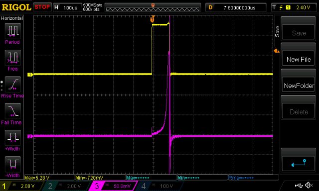
Increasing the pulse width increases the current flowing through the inductor.

I see that the E core inductor saturates very easily at about 5 to 6 Amps.
Higher purple curve slopes mean lower inductance and the sudden increase in slope is where saturation has begun. This test has subjected the inductor to about 110 Amps at the peak of the purple curve (200mv/1.82 = about 110 Amps)
We all know the current flowing in the primary windings of our inverters is usually much greater than 5A so that means this E core inductor is operating mainly under saturation. Instead of the inductor having a value of 94uH is has something far less, I estimate it is close to 3uH when the current is 40A.
3uH may as well be a 2 foot piece of wire...
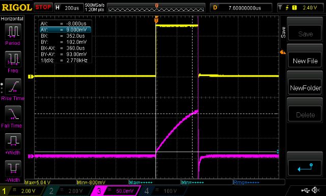
The ex-aerosharp choke behaves much better. It maintains it's 50uH up to 50Amps.

360us, 10V, (93mV/1.82)Amps means about 70uH
When you look at the info on the Aliexpress ready made inverter boards which in my view are very similar to what we have been building here, the instructions clearly state to use a 40uH inductor in conjunction with a 5uF cap on the 240V output.
I am starting to think that the E core inductors we are using are not quite right.
Certainly they are "good enough" for most people but maybe in some people's designs it is not good enough and causing real problems.
Later I will detail the home made inverter circuit, Arduino code, performance data etc.
Edited 2019-08-07 17:09 by Gizmo
wronger than a phone book full of wrong phone numbers