
|
|
Forum Index : Electronics : Various aspects of home brew inverters
| Page 1 of 48 |
|||||
| Author | Message | ||||
| poida Guru Joined: 02/02/2017 Location: AustraliaPosts: 1480 |
It's become clear to me I need to start a new topic. In it I will show what I have found, some puzzles that have me completely stumped and hopefully we can put some miscellaneous talk of bits and pieces of our home brew inverters here. I did not want to go off topic and hyjack Tinker's topic. Contents: Part 1: Primary Winding Inductors Part 2: Mains sync Part 3: Output waveform wiggles Part 4: Closely watched mosfet gate voltages Part 5: Experiments with the control loop Part 6: transformer resonance and a look at primary winding current Part 7: Primary current waveforms with different inductors plus efficiency calculations Part 9: Air core inductor possible or am I on drugs.. Part 10: sizing the inverter for my particular requirements and efficiency concerns Part 11: how does the PWM thing work? Just the basic idea.. Part 12: EG8010 variable output frequency Part 13: Phase locked loop control with Arduino Uno and Due Part 14: EG8010 Tfb signal behaviour Part 15: When 47uH is not the same as 47uH Part 16: BYO clock for the EG8010 Part 17: That Powerjack I bought. It has a primary choke. Part 18: primary current during transients Part 19: examining EG8010 pulse width modulation Part 20: where the wobbles come from Part 21: Change over from street to inverter and vice versa Part 22: Resonant frequency of the toriod/primary choke/secondary winding capacitor Part 23 examining output waveform shape as SPWM varies and as AC output frequency varies Part 24: thermal thoughts Part 25: How I log, process and view the data from my solar power system Part 25: generator waveforms (from the cheap Chinese 2 stroke genny) Part 26: A closer look at MOSFET gate voltages during switching Part 27: Why we make them big and beefy. (Inverters, that is) Part 28: Gate drive on Madness's power board. This uses on board transistor totem pole drive I have built a home made inverter using an Arduino microcontroller to drive the mosfet bridge. (more info later..) Part 1: Primary Winding Inductors I have been looking at the primary winding inductor lately. I bought a ferrite E core from RS, based on what other people have used around and about. I used one of these http://au.rs-online.com/web/p/transformer-ferrite-cores/6479345/ and have wound 3 1/2 turns. I firmly glued both halves of the E core together to stop the noise. The specs show it's AL value is 7900 uH/Turns squared Oztules and others use 3 or so turns on these things and when I measure the result with my core and the LCR meter I get 94uH. This is close to the theoretical value: 7900 uH * 3.5 *3.5 = 96.8uH So far so good. I also have a large common mode choke taken out of a 1500VA Aerosharp grid tie inverter. I unwound a lot of the winding to leave 13 turns and 50uH. Using this inductor I get a much cleaner output waveform compared with the ferrite E core. Why? I built an inductor tester, similar to what is shown here: http://ludens.cl/Electron/lmeter/lmeter.html but instead using an Arduino to create the short duty cycle pulses. My current shunt is a 2 cm length of copper wire. It's simple to derive the inductance, just use the simple formula L (inductance) = (Time x supply volts)/(rise in Amps) 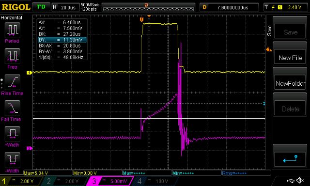 Yellow trace is gate drive for the mosfet. From the above we see time = 20.8us, supply is 10V from the bench PS and amps is the millivolts of the purple trace / 1.82 Using this tester of mine, I calculate the inductance as (20.8e6seconds * 10V)/(3.8/1.82) = 99uH Not bad for a rough test. Increasing the pulse width increases the current flowing through the inductor. 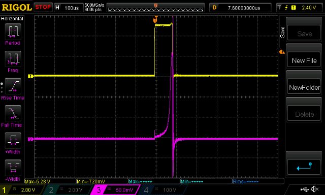 I see that the E core inductor saturates very easily at about 5 to 6 Amps. Higher purple curve slopes mean lower inductance and the sudden increase in slope is where saturation has begun. This test has subjected the inductor to about 110 Amps at the peak of the purple curve (200mv/1.82 = about 110 Amps) We all know the current flowing in the primary windings of our inverters is usually much greater than 5A so that means this E core inductor is operating mainly under saturation. Instead of the inductor having a value of 94uH is has something far less, I estimate it is close to 3uH when the current is 40A. 3uH may as well be a 2 foot piece of wire... The ex-aerosharp choke behaves much better. It maintains it's 50uH up to 50Amps. 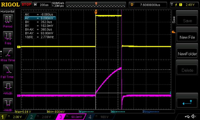 360us, 10V, (93mV/1.82)Amps means about 70uH When you look at the info on the Aliexpress ready made inverter boards which in my view are very similar to what we have been building here, the instructions clearly state to use a 40uH inductor in conjunction with a 5uF cap on the 240V output. I am starting to think that the E core inductors we are using are not quite right. Certainly they are "good enough" for most people but maybe in some people's designs it is not good enough and causing real problems. Later I will detail the home made inverter circuit, Arduino code, performance data etc. Edited 2019-08-07 17:09 by Gizmo wronger than a phone book full of wrong phone numbers |
||||
oztules Guru Joined: 26/07/2007 Location: AustraliaPosts: 1686 |
Nice to see some empirical testing on this.... not sure of the real relevance of the uh in this case. Why? It depends on what you think the inductor is actually doing, and at this stage the jury is out as far as I know.... someone must know, but it is not me. I think now that it has more to do with the rise time of the current into the transformer. So it is probably the first 200ns or so that is important in this instance... we need to get the thing driven, but the primary looks like a severe short circuit to a DC voltage.... 50mmsq wire is pretty hard on a 50-60v battery through a sub R load. As we are switching at 20khz, should we worry about that..... no, I calculate he turns for 50hz, so that can't be it. So I am left to look at the fast rise time of the DC, which gets faster the less resistance is in the transformer..... ie I am shorting the battery into the primary, the rise time will be a factor of the impedance... which is darn small. Working with electric fence units, I had the same trouble, and needed many triacs to cover the dumping of 60uf@ 700v into a short circuit primary of only 18t of 1.8mm (x2)wire.... here we were talking hundreds of thousands of watts, and a small coil of 30 turns on air or ferrite to take the shock out of it, and allows for the same performance with only a single triac. So it looks like the fast rise time of the input current is what we are trying to curtail.... In the fencer example, the air coil can be replaced with a smaller ferrite ring, and the same results are gained... so I also know that the saturation is immaterial to the outcome, and probably helps to keep the impedance down once the current really flows... ie the air coil was no different in the end to the ferrite torroid. So why did I put the inductor in there.... to keep the idle current down.... nothing else. I think it keeps it down because in the first few hundred nano seconds, the inductor actually works on the fast rising wave front of the DC into the transformer primary, as though it feels like a multi megahertz wave front ( 100mhz?).... it is not?. It is the leading edge of the rise of the pwm wave of the 20khz, and may be only <.1% of the 20khz time window... so it may be say 1000 x 20khz or less.. or more..... but whatever it is, it is very very fast, and it is related to the transformer primary impedance.. ( as was the time width of the wave from the fencers.... high impedance = wide waveform) So if we can garner a few uh for a few nano seconds, it 's job is done. After that we don't need to care, and in the real world this seems to be the case. The other boards you refer to 40uh if you look at the picture of the one they recommend, it is a ferrite ring... it would saturate in a heart beat, so they also seem to agree that it is useful for only a small part of the pwm wave. It has been tested , and found that more uh is not necessarily better, and Andrew on another forum who also wound inductors on the original W7 on energy matter site, had a inductor he calculated on the 20khz..... and it was much worse than the 3.5 turns on the ecore. Like Tinker, I like the ferrite ring, as it is very quiet, and I am prepared to try the aerosharp if we can get the wire into it easily. But I am still not sure we need to do much better with the ferrite inductor, as I still don't really have a good idea what I was doing with it in the first place. I do really like the research you have put into it though, and it explains to me better what I may think I have seen to date. And I whole heartedly agree with you that the inductors I use in particular are not quite right.. or maybe even remotely right, but they seem to work fine for what they are purposed for. If we can find a better alternative through your efforts, it will be a big bonus. I do know it effects the wave form of the sine wave sometimes.... we need to know a lot more about this, and I am hoping you can do it too. The ringing does not look good  ........oztules Village idiot...or... just another hack out of his depth |
||||
| Warpspeed Guru Joined: 09/08/2007 Location: AustraliaPosts: 4406 |
[quote]I think it keeps it down because in the first few hundred nano seconds, the inductor actually works on the fast rising wave front of the DC into the transformer primary, as though it feels like a multi megahertz wave front ( 100mhz?).... it is not?. It is the leading edge of the rise of the pwm wave of the 20khz, and may be only <.1% of the 20khz time window... so it may be say 1000 x 20khz or less.. or more..... but whatever it is, it is very very fast, and it is related to the transformer primary impedance.. ( as was the time width of the wave from the fencers.... high impedance = wide waveform) So if we can garner a few uh for a few nano seconds, it 's job is done. After that we don't need to care, and in the real world this seems to be the case.[/quote] Yes, very nicely put Mr oZ. Our mosfet has three distinct states. Off when it is completely open circuit, and on when it has a very low resistance (a few milliohms). The third state is while it is in the process of turning either on or off, where it goes through a very rapid change of resistance. It cannot go instantly from off to on, or from on to off, there is some very short time interval where the resistance is actually changing. Now that is a very big problem for us, because at some stage in the switching process both the voltage across the mosfet will be high, at the same time as the current is also very high. That causes a MASSIVE spike in internal power dissipation. The faster you can make it switch, the shorter duration the heat spike will be. But there are obvious practical limits to how fast any circuit can be made to switch. You cannot make the heat spike smaller, only narrower by speeding things up. So we need another way to get around this particular problem. One solution is to put a very small inductor in series with the mosfet. What then happens is that the mosfet turns on taking perhaps 100nS to do so, the rate of current rise is limited by the new added inductance. What we want is for the inductance to be high enough for 100 nS (in this example) to hold back the current until the mosfet resistance has fallen down to the milliom region, then for the inductance to completely go away. We can do that by winding a very few turns onto a ferrite core that has very high permiability (inductance per turn) but saturates at a low current. As long as the inductor can hold back the initial rise of current for a very short period, that is all it has to do. The mosfet can switch on under low current conditions, held back by the inductor, and once its turned on really hard, the inductor saturates and the current can THEN really spike upwards, but the heat and dissipative power loss is no longer there. So there is no real surprise that fitting an optimum turn on snubber inductance significantly lowers inverter no load switching loss. There is a tradeoff here between the magnetic properties of the core, how many turns, and mosfet switching time. Too few turns and you don't get enough initial inductance. Too many turns and it will saturate too quickly before the mosfet has a chance to turn fully on. Its all a bit of a guess without being able to actually see and measure what is going on with appropriate equipment. What works well in one set of operating conditions, may not be optimum for someone else. So its a case of trying a few things and tweaking by trial and error for minimum turn on switching loss. That should be reflected in reduced inverter idling current. There is no real mystery in what it does. The magic is getting it to work exactly right for YOUR inverter, which is always going to be a bit different than someone else's, particularly with home brew projects. Its a bit different for commercial production where all units are almost identical. Cheers, �Tony. |
||||
| oztules Guru Joined: 26/07/2007 Location: AustraliaPosts: 1686 |
Thanks Tony, I feel like I might not be as mad as I previously presupposed  I have enough ignorance to seemingly keep inventing/finding things that everyone already knows. There is a possibility that as everyone winds different transformers, the input impedances are all different, and so the wave front on everyones units will be different , and so require slightly different inductors. The stiffer the primary, the faster the input spike will try to be, is what I found out with the fencer units.... I have seen up to 400kw in those things ( yes really, 10000v@40 amps measured with the Gallagher fence testers.). Look forward to more stuff from Poida.... pretty excited to see this thread evolve. ...........oztules yes.... small things amuse small minds  Village idiot...or... just another hack out of his depth |
||||
| Warpspeed Guru Joined: 09/08/2007 Location: AustraliaPosts: 4406 |
Yes its all interesting stuff. This magic inductor needs to be ferrite. Toroids or EE cores being ideal. That will give high initial permiability, but it will also saturate very quickly which is good. Powdered iron cores are less than ideal because they are much more difficult to saturate than ferrite. In other words the inductance does not go away quite as well during high power operation. I am becoming increasingly suspicious about some of the parts that originate from China, and particularly with power mosfets and magnetic cores. Powdered iron is dirt cheap, but ferrite is much more expensive to produce. Ah so, lovely Chinese ferrite toriod, very nice, very cheap, you buy many yes ? Maybe just one to try first haha. As to why these small inductors can sometimes do really strange things to the output waveform, I have absolutely no idea. Cheers, �Tony. |
||||
Madness Guru Joined: 08/10/2011 Location: AustraliaPosts: 2498 |
There is a fourth state of MOSFETs when they sh#t themselves :) There are only 10 types of people in the world: those who understand binary, and those who don't. |
||||
| Warpspeed Guru Joined: 09/08/2007 Location: AustraliaPosts: 4406 |
I love the smell of burning silicon in the mornings.  Cheers, �Tony. |
||||
| Madness Guru Joined: 08/10/2011 Location: AustraliaPosts: 2498 |
LOL great movie, I knew what you were referring to before I saw the image. There are only 10 types of people in the world: those who understand binary, and those who don't. |
||||
| poida Guru Joined: 02/02/2017 Location: AustraliaPosts: 1480 |
It's my firm view that mosfets feel no pain. It was mentioned in another forum (http://www.anotherpower.com/board/index.php/topic,1228.msg13370.html#msg13370) that maybe syncronising to mains might be a good idea to look at since the EG8010 has no capability to do so. Part 2: Mains sync I have a few Arduino boards, mainly using the ATMega 328P (Uno boards, and similar) and also a couple of Due boards using Atmel SAM3 chips running at 84MHz which is much faster than the Uno at 16MHz. The SAM3 chips have a 32bit ALU compared with the 16bit Uno. I have my inverter test code runnning on a Due and wanted to get it to sync to an external input. For testing, the input will be a square wave, to gently introduce me to the ugly concepts of phase and frequency feedback loops. The Due is about 4-10x faster in most things and it has a huge data + program memory. After a few hours I have a PLL working quite nicely, and you can see it in the below video https://youtu.be/F_hK1rfKssE What to look for is the frequency of the input, shown at top right. The yellow trace is input, the blue is low pass filtered 20KHz PWM output of the inverter program. Note how it can track and lock onto the small changes I make to the input signal. This was scary easy to hack up a quick feasibility test. I found a document looking at AUS electric network frequency standard and it seems network connected mains will be 49.9 to 50.1Hz when running normally, and 49.75 to 50.25Hz during an unplanned outage. Island or separated systems (Hello Oztules!) have a standard of 49-51Hz for normal running. So the PLL does not need to lock on to and follow freq/phase changes of large proportions just +/- 0.5Hz or so. How rapid will these excursions occur? Any information I can read online? So at first glance I think I can do this. There then appear very significant issues such as: - should we ever do this? - when not in sync, the inverter will blow it's self to bits. How to protect against this? - maybe OK for advanced DIY systems on electrical islands (hello Oztules! again) - maybe OK in un(der) regulated jurisdictions - I would probably be hung by the neck if I do this here in OZ But it's fun to have a look at how and why... The PLL work has another application and that is syncronising to another inverter. This will let us design multiple units to run under a single regime. rough program: 1/ during each 50Hz output, locate rising edge of external sync and record when it happens. 2/ at the end of the 50Hz wave, update both the 50Hz PWM period counter and the 20KHz SPWM so as to have the future output closer to the external sync phase and freq. code snippets: 1/ // all 16 bit integer math so it runs fast. This code runs about 300KHz so it's called // very often so as to get best estimate of rising edge. u = ADC->ADC_CDR[6]; // fast read of ADC channel 2 on Due if(psc < 300) // only look for the edge in first 3/4 of 50Hz output { // u1, u0 get set to -1 at start of each 50Hz cycle elsewhere if (u > 1500) // threshold for HI/LOW test of ext sync u1 = 1; else u1 = 0; if (u1 == 1 && u0 == 0) // we have the transition from low to high now uedge = REG_PWM_CCNT1; // so record PWM clock source counter u0 = u1; } if(psc == 200) // at end of 1/2 50Hz cycle, check ext sync { // to determine leading or lagging phase if (u > 1500) { usign = 1; } else { usign = -1; } } 2/ // this runs once at the beginning of each 50Hz output cycle. // burstcount++; if(burstcount > 3) // only alter the 50Hz period counter once each 4 times { // most importantly, the change in the period counter burstcount=0; // for phase differences is not cumulative pburst = (uedge - 26250)/4; // PWM period change value, if uedge = 26250 then } // ext sync is exactly in phase else pburst = 0; u = abs(uedge - 26250); u2 = u2 - usign*(1+u/256); // need a trim factor for frequency which is cumulative REG_PWM_CPRDUPD1 = 52500 + u2 + pburst; // update 50Hz PWM period register REG_PWM_CDTYUPD1 = (52500 + u2 + pburst)/2; // and maintain 50% duty cycle with new period REG_PWM_CPRDUPD0 = PPWM + u2/10; // also change 20kHz period reg to suit shorter or longer // "50Hz" output wronger than a phone book full of wrong phone numbers |
||||
| Warpspeed Guru Joined: 09/08/2007 Location: AustraliaPosts: 4406 |
I intend to get me one of these EG8010 boards, to torture to death, just for fun. They are so cheap and I am a curios kind of guy... Do not forget, that anything that runs on software, somewhere has a crystal or a resonator to generate the appropriate Mhz heart beat for the processor. We can be fiendishly cunning and replace that with a voltage controlled oscillator, and then lock the PWM 50Hz output of our EG8010 board to the mains directly with a bit of very simple external hardware. No need to molest the software at all. We can make it run fast or slow and phase lock it solid to the grid, and if the grid dies it just plods on unknowing only very slightly off frequency which will not matter. In my own own system, I rectify grid power to high voltage dc, then turn that back into 50Hz sine wave power to power my home. All done at high voltages and relatively low current, so its very efficient. My home brew inverter is not mains locked, and there is no need for to be. Cheers, �Tony. |
||||
| Madness Guru Joined: 08/10/2011 Location: AustraliaPosts: 2498 |
In the link you mention Poida I gave the parameters that my Trace Inverter uses for both grid and generator synchronisation. It uses a range of 3 Hz above and below the target of 50, once it goes out of that range the Inverter disconnects. Many people with off-grid Inverters would benefit from the ability to charge off a generator. They will not hold exactly the same frequency and will tend to drift a bit particularly with load fluctuations. The Trace has 2 AC inputs and will work with grid and generators, there are several modes, one of these is to regulate the battery voltage using the grid to dump the excess power when available. If you use Oztules idea of using panels that have maximum power at 30 volts and have these in strings of 2 for a 48 Volt system. Then you can have no charge controller other than the Inverter connected to the grid to divert the extra power. If there is low battery voltage then it could also charge from the grid as required. There are only 10 types of people in the world: those who understand binary, and those who don't. |
||||
| poida Guru Joined: 02/02/2017 Location: AustraliaPosts: 1480 |
Warpspeed: of course the best way to go is to drive the clock input yourself. Hardware locked PLL would be the best. But I like hacking up something to have a play. Part 3: Output waveform wiggles We all must have seen the AC output wiggles and wondered where it comes from. These wiggles take different forms depending on the builder and his choice of transformer primary windings, AC output capacitors and inductors. Other factors can effect this too. It's important for this discussion to accept that the circuit we have in our inverters is an LC tank that resonates when given any reason to do so. It has some dampening which permits out inverters to function fine (or not). It's actually a LCR series thing but it behaves like an LC tank. The circuit is driven by the mosfet bridge, then one wire has an inductor in series, then the primary winding (with additional inductance) then back to the other bridge output. There is a capacitor connected in parallel with one or more inductances. There is some series resistance from the primary winding wire, primary inductor wire etc. This helps dampen the oscillations. I think I have found the cause of these wobbles in the AC output waveform. First some examples of mine: 13 turns on the Aerosharp output choke (not very large but they ARE there.) 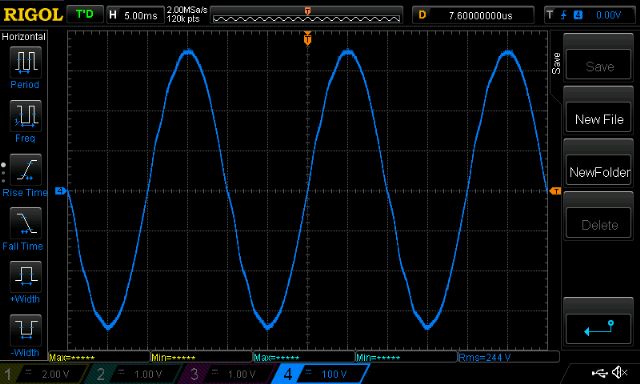 8 turns of thicker wire on same choke (still there..)  3 1/2 turns on a TDK E core "E 65/32/27" as used by Oztules and others. I wonder why it is asymmetrical? 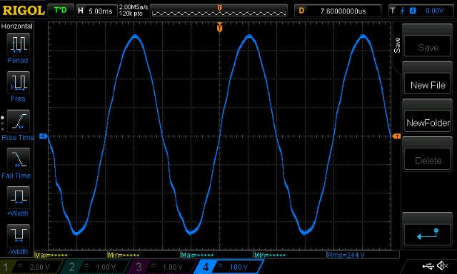 In all cases you can see wiggles in the sine wave immediately as it passes zero. These wiggles reduce to nothing about at the top or bottom of the waveform. My oscilloscope can perform math on a waveform, so I show a high pass filtered trace (purple) of the output AC alongside the original AC waveform. High pass filter removes the 50Hz part of the waveform. 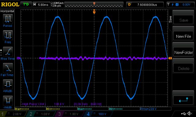 We need to shift the filtered trace leftwards about 1 division to line up with the source. Notice there is some oscillation that is damped and dies out after a few cycles. We all have had this to some degree. Sometimes the oscillations are damped out really quickly and so we see just a step up/down as the AC output passes zero. 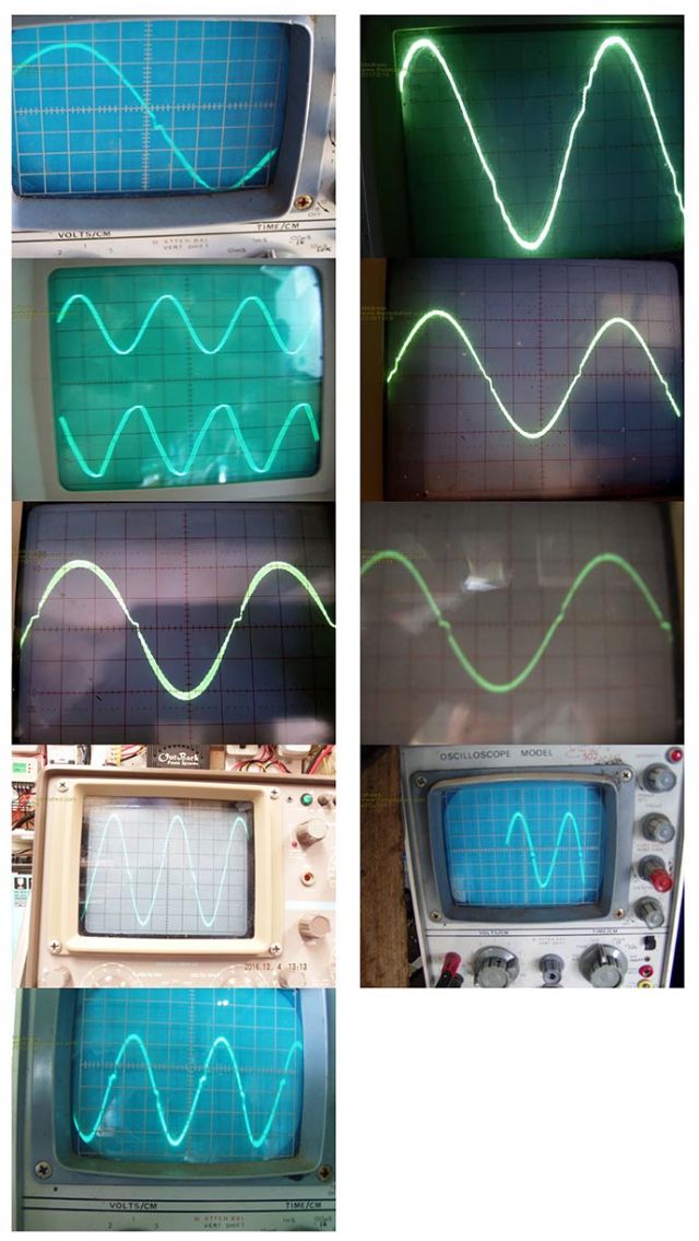 (let's play spot my CRO trace...) Anyway, all that is just my view. I modeled a PWM sinewave driving the same LC tank circuit and you would not believe what I saw. If you have access to Multisim v.11 you can download the circuit below. Here is the PWM output alongside the sinewave that is modulating the PWM. Red is sinewave modulation for PWM, yellow is LC filtered PWM output which is supposed to represent the AC output waveform from an inverter. 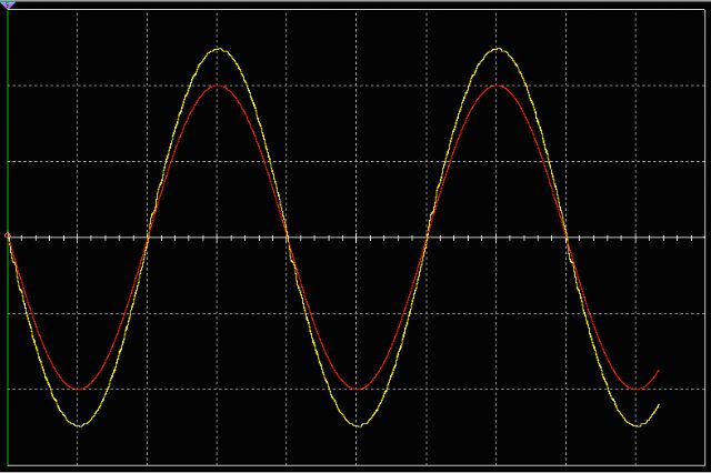 You can clearly see the wiggles appear after each zero crossing. They die out after a few wobbles. The simulation lets me modulate the PWM with any waveform. I tried a square wave. 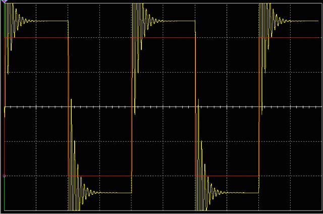 When I saw this, I finally understood the consequences of connecting an LC tank circuit to the output of the mosfet bridge. It will oscillate, the only question is how much damping there will be, how strongly the oscillations will be excited and the amplitude and frequency. The simulation employs a 20KHz PWM, output into a 130uH and 50uF LC tank. These values are close to the sort of values we use in our inverters. The simple "step" immediately after each zero crossing can be seen in some people's devices. This is an oscillation, but it is a highly damped one. It dies out after 1 half cycle or so. It's cause is the same, only it's effected by different L,C and R parameters. So, that's that. The mystery to my mind is solved. It's something we live with if we want to run the inverter at the bleeding edge of efficiency with massive primary windings, little primary inductance and a decent AC output capacitor. It will oscillate and that's that. Some people think these steps and oscillations are due to imperfect PWM modulation by the EG8010 around the zero crossing. At the time a little before, during and a little after the zero crossing, the PWM must be off completely to deliver zero volts to the primary. Then the first pulse of PWM that is trying to generate a small increase in voltage (from zero) is seen by the tank circuit as a highly energetic single and short squarewave. This makes the circuit ring like a bell. I do not think these wigggles are the direct result of insufficently correct PWM. It's what you get from hitting a LC tank with a hammer. I look forward to any discussion on this topic. 2017-03-10_110432_bipolar_SPWM_shows_oscillation.ms11.zip wronger than a phone book full of wrong phone numbers |
||||
| Madness Guru Joined: 08/10/2011 Location: AustraliaPosts: 2498 |
In my case I don't get these wiggles with a few FET's when I have 4 and upwards the wiggles turn into spikes. I hope you are able to get the bottom of it, I am running out of ideas and enthusiasm. There are only 10 types of people in the world: those who understand binary, and those who don't. |
||||
| Warpspeed Guru Joined: 09/08/2007 Location: AustraliaPosts: 4406 |
Well done Poida. It seems the transformer, and the components immediately around the transformer can have multiple resonances with various amounts of coupling and damping, also influenced by the nature of any inverter output load. Its all a bit of a dog's breakfast and very difficult to analyse. Adding our primary snubber inductor will also influence all of that as we already know. Looking at the awful waveforms coming straight off the grid, I would not lose any sleep over a few low amplitude wiggles. Cheers, �Tony. |
||||
| oztules Guru Joined: 26/07/2007 Location: AustraliaPosts: 1686 |
Poida's insights are truly amazing revelations.....good work. There are a few twists and turns to be unravelled too. Sometimes the 8010 will change load requirements instantly, but the transformer noise changes very slowly. It may go silent and be pulling 6kw, then after a few seconds of "catching up with requirements, and running steady at the new power level", the wobbles can come back in, and the transformer changes sound, from silent to quiet running. It would be nice to have the silent running part all the time. Different transformers have different sounds, and that may be explained now by the resonances. Is it possible the 4 fets no wobbles, and 6 fet wobbles is because the impedance presented by more fets is lower, and the resonant frequency changes from out of range to in range perhaps. Mad, have you run the new drivers yet to see if they stop the wobbles? If they make no difference, then Poida is probably spot on the money. .........oztules Village idiot...or... just another hack out of his depth |
||||
| Madness Guru Joined: 08/10/2011 Location: AustraliaPosts: 2498 |
I have not got the new drivers running properly yet, I have had it running with no transformer but when the transformer is connected the TC4452's are failing as soon as the soft start completes. This may be due to the way I bodged them into an existing board so working on new power board with the additional drivers included directly on the PCB. All going well I will have that board completed this weekend. There are only 10 types of people in the world: those who understand binary, and those who don't. |
||||
| poida Guru Joined: 02/02/2017 Location: AustraliaPosts: 1480 |
Madness: I can't help you with your mosfet exploding issue. It's beyond my understanding at the moment and likely will be for a while. Oz: I agree - when changing the no. of fets the series resistance changes (when ON) and so the tank will behave differently with more or less damping. I have my prototype inverter (i.e. arduino driven one) running with the 3.5 turns in the E core. IT starts up up fine and runs fine. The strange thing is it takes about 1 second after full voltage to be reached and PID in control for a strange, asymetrical wiggle appear in output AC. Extra transformer noise appears too. It seems to me that something is not quite resonant but waiting for the needed excitation to arrive, then it resonates. I can make the transformer make louder noises when I increase AC output setpoint, and when I reduce setpoint, no noise in transition, but after a few seconds, it returns. This also is present in the EG8010 controlled aliexpress inverter boardbut a little less. The E core does strange things when wound with thick wire to my test systems. Thanks for all your comments. wronger than a phone book full of wrong phone numbers |
||||
| Tinker Guru Joined: 07/11/2007 Location: AustraliaPosts: 1904 |
|
||||
| oztules Guru Joined: 26/07/2007 Location: AustraliaPosts: 1686 |
Poida, Thats exactly what I am talking about.... no noise in transition, even at very high power levels, but can get noise at steady state operation... weird..... It takes a few seconds at steady state for the noise to arrive. Maybe you can program for minor movements in the pwm pulse to keep the noise and wiggle out, but not materially affect the voltage.... ie two step forward and one step back, and then two back and one forward for steady state... i have no idea really..... as we are changing the pulse width all the time already to make the wave in the first place... so whats different when we change load or voltage? Unless there is some asymmetry when we are moving to more power or higher voltage in the waveform we can't really see, but enough to stop the resonance.... maybe we need to not have a mirror image in the quadrants, but a slightly asymmetrical sine wave?? .....oztules Village idiot...or... just another hack out of his depth |
||||
| Madness Guru Joined: 08/10/2011 Location: AustraliaPosts: 2498 |
Hi Poida, Please excuse my ignorance but could you post a photo or a bit information about this choke please. I only have 3000W Aero-sharps. There are only 10 types of people in the world: those who understand binary, and those who don't. |
||||
| Page 1 of 48 |
|||||
| The Back Shed's forum code is written, and hosted, in Australia. | © JAQ Software 2026 |
